Dual-impeller for centrifugal blower

A centrifugal fan and double impeller technology, which is used in mechanical equipment, machines/engines, liquid fuel engines, etc., can solve the problems that the flow range cannot meet the industrial requirements, the fan installation space is limited, and the air volume change range is large, and the thickness can be increased. , Improve the operating range, the effect of uniform airflow speed

Inactive Publication Date: 2015-05-20
ZHEJIANG SCI-TECH UNIV
View PDF5 Cites 4 Cited by
  • Summary
  • Abstract
  • Description
  • Claims
  • Application Information

AI Technical Summary

Problems solved by technology

Different types of fans are selected according to the air volume requirements of different industrial applications. However, with the rapid development of industries at home and abroad, the air volume in many industrial places varies widely, and the fan installation space is limited.
If a fan with a small flow rate is used, its flow range cannot meet the industrial requirements; if a fan with a large flow rate is used, when the air volume is small, there will be a phenomenon of "big horses and small carts", and the energy consumption will be large

Method used


Image

  • Dual-impeller for centrifugal blower
  • Dual-impeller for centrifugal blower
  • Dual-impeller for centrifugal blower

Examples


Embodiment Construction

[0024] The present invention will be further described below in conjunction with the accompanying drawings and embodiments.

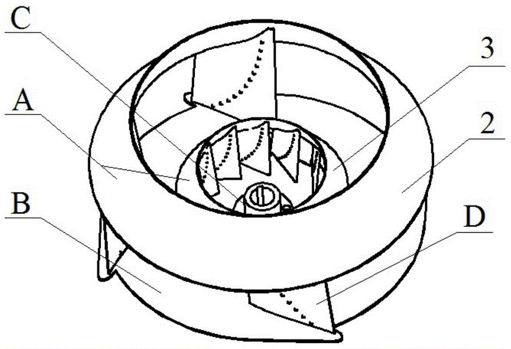
[0025] Such as figure 1 , 2 As shown in and 3, a double impeller for a centrifugal fan includes an outer impeller 2 and an inner impeller 3, and the outer impeller 2 is sleeved outside the inner impeller 3; the outer impeller 2 and the inner impeller 3 both include a wheel cover A and a wheel disc B , shaft disk C and blade D; the shaft disk C of the outer impeller 2 and the shaft disk C of the inner impeller 3 are supported on two power input shafts through bearings; the two power input shafts are arranged coaxially and input power respectively.

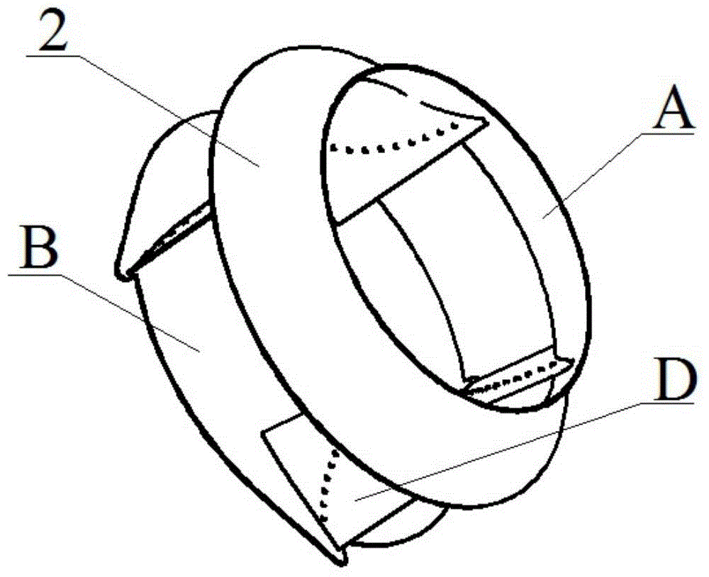
[0026] Such as figure 2 As shown, the disc B of the outer impeller 2 is fixed on the shaft disc C, and the four blades D are evenly distributed along the circumferential direction, one side is fixed on the outer edge of the disc B, and the other side is fixed to the wheel cover A.

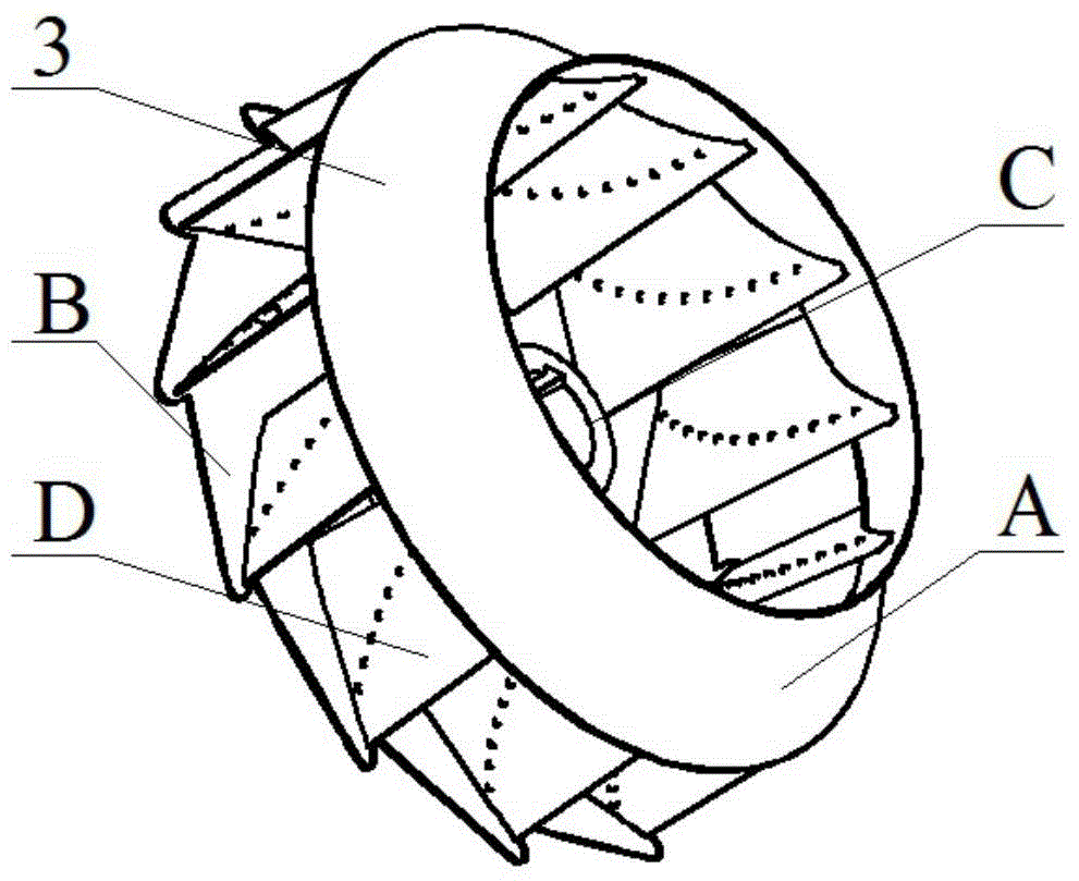
[0027] Such as image...


PUM


Abstract

The invention discloses a dual-impeller for a centrifugal blower. In many industrial sites, the change range of air volume is large, and the flow ranges of small-flow draught fans can not meet the requirements; large-flow draught fans are high in energy consumption when the air volume is small. The dual-impeller comprises an outer impeller and an inner impeller. The surface of each blade is provided with floatable protrusions. The floatable protrusions are in socket joint with the surfaces of the blades through hinged bars. A cavity of each blade is internally and fixedly provided with a transverse reinforcing plate and a plurality of oblique reinforcing plates. A wheel disk flow deflector is fixedly arranged at the position, located under each blade, of a wheel disk of the inner impeller, and a wheel disk flow deflector is fixedly arranged at the position, located under each blade, of a wheel disk of the outer impeller. Different impellers can be selectively switched on according to the requirement for air volume, the reasonable running range of the centrifugal blower can be expanded, and the airflow pressure of the centrifugal blower can be increased, so the centrifugal blower achieves multiple functions; the inner impeller and the outer impeller are switched on simultaneously, the inner impeller does work to low-speed fluid at the corresponding wheel disk, the airflow speed difference of inlets of the blades, the wheel disks and wheel covers can be effectively reduced, and the airflow speed at the inlets of the blades is more uniform, so efficiency is improved, and noise is lowered.

Description

technical field [0001] The invention belongs to the field of ventilation equipment and relates to a centrifugal fan, in particular to a double impeller for the centrifugal fan. Background technique [0002] As a relatively common mechanical equipment, fans have been greatly improved with the development of social science and technology. The development of domestic industry has further stimulated the use of fans, and the use of fans has attracted more and more attention from users. In today's energy shortage in our country, energy saving and consumption reduction is the dream goal of many users, but there is always a lot of waste in the daily use of fans, which increases the economic cost of users. Therefore, it is imperative to improve the efficiency of fans Row. [0003] Centrifugal fans are mainly composed of collectors, impellers, volutes and diffusers. The gas is directed to the impeller through the collector, and the pressure increases under the action of the rotation...

Claims


Application Information

Patent Timeline
Patent Type & Authority Applications(China)
IPC IPC(8): F04D29/28
CPCF04D29/28F04D29/30F05D2240/31
Inventor 窦华书肖美娜魏义坤陈小平杨徽
Owner ZHEJIANG SCI-TECH UNIV
Why Eureka
Try Eureka