Centrifugal pump with ultrasound flow-through measurement device

A technology of rotary pump and flow measurement device, applied in liquid/fluid solid measurement, measurement flow/mass flow, pump control, etc., which can solve the problems of reducing the volume flow range and deteriorating measurement accuracy.

Active Publication Date: 2015-05-20
WILO SE
View PDF13 Cites 1 Cited by
  • Summary
  • Abstract
  • Description
  • Claims
  • Application Information

AI Technical Summary

Problems solved by technology

If the required structural dimensions cannot be implemented in the pump or system depending on the construction, and the sensors are installed with a shortened measuring path, the sensors react with degraded measuring accuracy and possibly lead to a reduction in the usable volume flow range

Method used


Image

  • Centrifugal pump with ultrasound flow-through measurement device
  • Centrifugal pump with ultrasound flow-through measurement device
  • Centrifugal pump with ultrasound flow-through measurement device

Examples


Embodiment

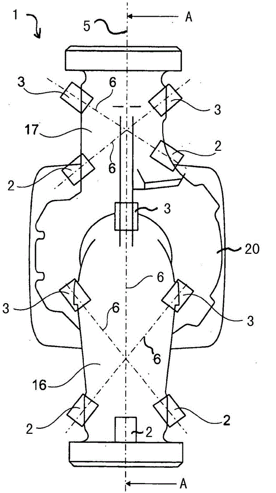
[0129] The pump according to the invention can be a solar pump in which, for example, a flow measuring device for heat detection (revenue detection) is integrated. In general, the pump according to the invention can be integrated in a solar system for function control. Alternatively, the pump may be a fresh water station pump, a heat pump or a metering pump. As a heat pump, the flow measuring device can also be used for heat metering. Finally, the flow measuring unit can also be used for power measurement or power regulation of pumps or pump systems. The pump 1 can be a wet rotor or a dry rotor.


PUM


Abstract

The invention relates to a centrifugal pump (1) for conveying a liquid, comprising an impeller (21) which is arranged in a pump chamber (20), and one suction nozzle (16) and one pressure nozzle (17) which are both attached to the pump chamber (20). The centrifugal pump comprises an ultrasound-based flow-through measurement device (2, 3, 18) which has at least two ultrasound units (2, 3) for emitting and/or detecting ultrasound pulses and which are internally located in or on the suction nozzle (16), pressure nozzle (17) and/or the pump chamber (20). At least one measurement line (6) is formed between the ultrasound units (2, 3), along which measurement line at least one first ultrasound pulse, which can be emitted upstream by one of the ultrasound units (2), can be detected by another of the ultrasound units (3) and at least one second ultrasound pulse, which can be emitted downstream by one of the ultrasound units (3), can be detected by another of the ultrasound units (2). The flow-through measurement unit (2, 3, 18) also has a sensor electronics unit (18) for measuring a runtime difference between the first and the second ultrasound pulses and for determining a flow-through of the centrifugal pump (1) on the basis of the runtime difference.

Description

technical field [0001] The invention relates to a rotary pump, which is used for conveying liquid. The rotary pump includes a working wheel arranged in a pump chamber, and a suction connecting pipe and a pressure connecting pipe respectively connected to the pump chamber. Background technique [0002] To determine the operating point of the pump, instead of the volumetric flow, the actual value of the absolute pressure on the pressure side or the pressure difference between the pressure side and the suction side of the pump (as an equivalent value for the head) is preferably used. The differential pressure method is usually only used in higher power or price class pumps based on cost. [0003] Alternatively use separate "stand alone" volume flow sensors in installations (such as heating installations, drinking water installations, fresh water installations, solar installations, etc.) that respond to the volume flow according to the most different sensor Principle, eg direct...

Claims


Application Information

Patent Timeline
Patent Type & Authority Applications(China)
IPC IPC(8): F04D15/00G01F1/66
CPCF04D15/0088G01F1/66G01F1/662G01F1/666F05D2270/3061F05D2270/806
Inventor E·布津斯基
Owner WILO SE
Why Eureka
Try Eureka