
Rotary adjusting bracket structure and camera shooting instrument

A technology of rotating bracket and bracket structure, applied in the field of cameras, can solve the problems of inconvenient adjustment operation and discontinuous adjustment range, and achieve the effect of continuous adjustment range

Active Publication Date: 2015-05-27
SHENZHEN INFINOVA
View PDF8 Cites 7 Cited by
  • Summary
  • Abstract
  • Description
  • Claims
  • Application Information

AI Technical Summary

Problems solved by technology

[0005] The purpose of the present invention is to provide a rotating adjustment bracket structure and imaging equipment, aiming to solve the problems of discontinuous adjustment range and inconvenient adjustment operation in the multi-directional adjustment of the prior art video camera

Method used


Image

  • Rotary adjusting bracket structure and camera shooting instrument
  • Rotary adjusting bracket structure and camera shooting instrument
  • Rotary adjusting bracket structure and camera shooting instrument

Examples


Embodiment Construction

[0023] In order to make the object, technical solution and advantages of the present invention clearer, the present invention will be further described in detail below in conjunction with the accompanying drawings and embodiments. It should be understood that the specific embodiments described here are only used to explain the present invention, not to limit the present invention.

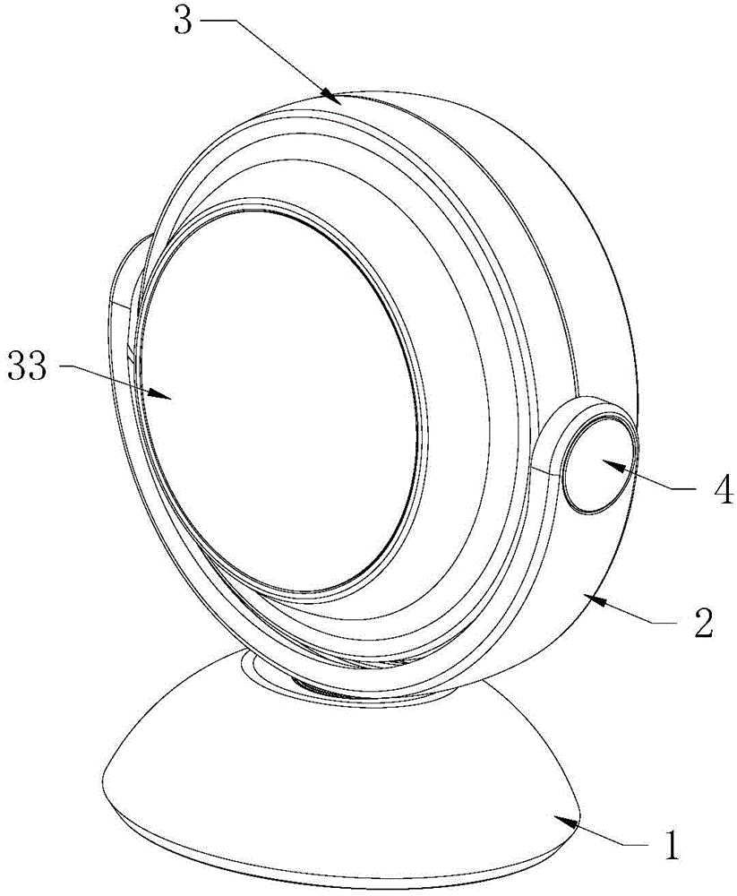
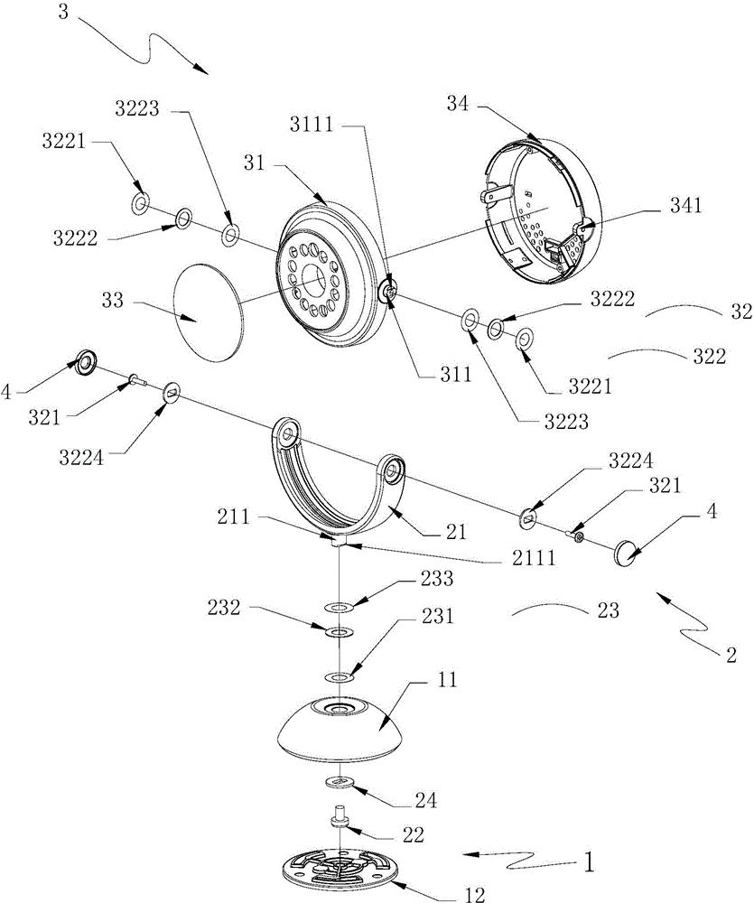
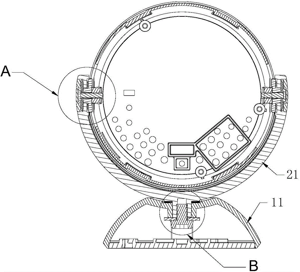
[0024] Such as Figure 1 to Figure 6 As shown, it is an example diagram of the rotation adjustment bracket structure provided by the embodiment of the present invention, which includes a base 1, a first rotation bracket assembly 2 arranged on the base 1 and rotatably connected with the base 1, and a first rotation bracket assembly 2 Rotationally connected spherical shell assembly 3, wherein the base 1 includes a bottom shell 12 and a bottom cover 11 covered on the bottom shell 12, the bottom cover 11 is bowl-shaped, and the first rotating bracket assembly 2 includes a bottom cover 11 arranged on th...


PUM


Abstract

The invention is suitable for the technical field of cameras and discloses a rotary adjusting bracket structure. The rotary adjusting bracket structure comprises a base, a first rotating bracket assembly and a spherical shell assembly, wherein the first rotating bracket assembly is connected with the base in a rotating way; the spherical shell assembly is connected with the first rotating bracket assembly in the rotating way; the base comprises a bottom cover; the first rotating bracket assembly comprises a rotating bracket arranged above the bottom cover; a camshaft is arranged at the bottom of the rotating bracket; a threaded hole is concavely formed in the bottom surface of the camshaft; the first rotating bracket assembly further comprises a first screw and a first elastic cushion assembly, and the first screw is connected with the threaded hole of the camshaft, and the first elastic cushion assembly is arranged on the camshaft in a sleeving way and enables the rotating bracket to rotate around the first screw and then to be positioned; the camshaft penetrates through the bottom cover and then is connected with the first screw through threads. According to the rotary adjusting bracket structure disclosed by the invention, the first screw is connected with the camshaft arranged on the rotating bracket through the threads, and the first elastic cushion assembly is arranged on the camshaft in the sleeving way, so that the rotating bracket rotates around the first screw and then can be instantly positioned, and the rotating bracket can be rotated and adjusted without tools; in addition, the adjustment range is continuous.

Description

technical field [0001] The invention belongs to the technical field of cameras, and in particular relates to a rotation adjustment bracket structure and a camera instrument. Background technique [0002] With the development of Internet technology, cloud technology and smart home, the civilian market has become an important direction for camera design and positioning, and industrial cameras are gradually moving closer to consumer electronics. The absence of external fastening screws can ensure the integrity of the product, make the product more beautiful, and enhance the competitiveness of the product. This is an important aspect pursued in the design of consumer electronics products. However, products without external fastening screws have the following two problems: Two problems: 1. It is not easy to disassemble and maintain; 2. It is easy to separate and damage when dropped. [0003] During the actual installation and use of the camera, it must have a multi-directional a...

Claims


Application Information

Patent Timeline
Patent Type & Authority Applications(China)
IPC IPC(8): F16M11/22F16M11/06F16M11/18H04N5/225
Inventor 张谢恩
Owner SHENZHEN INFINOVA
Learn More