Locking buckling mechanism

A locking mechanism and locking technology, applied to structural parts, instruments, electrical digital data processing, etc., can solve problems that cannot be dealt with, and achieve the effect of improving inclusiveness

Inactive Publication Date: 2015-05-27
INVENTEC PUDONG TECH CORPOARTION +1
View PDF4 Cites 6 Cited by
  • Summary
  • Abstract
  • Description
  • Claims
  • Application Information

AI Technical Summary

Problems solved by technology

Using both hands to operate in this way will naturally bring various inco

Method used


Image

  • Locking buckling mechanism
  • Locking buckling mechanism
  • Locking buckling mechanism

Examples


Example Embodiment

[0054] Hereinafter, a number of embodiments of the present invention will be disclosed in drawings. For clear description, many practical details will be described in the following description. However, it should be understood that these practical details should not be used to limit the present invention. That is, in some embodiments of the present invention, these practical details are unnecessary. In addition, in order to simplify the drawings, some conventionally used structures and elements will be shown in a simple schematic manner in the drawings.

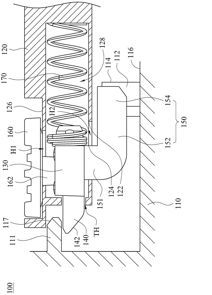
[0055] figure 1 A cross-sectional view of the locking mechanism 100 after the first structure 110 and the second structure 120 are combined according to an embodiment of the present invention is shown. Such as figure 1 As shown, a locking mechanism 100 includes a first structure 110, a second structure 120, a moving part 130, a lock head 140 and at least one hook 150. The first structure 110 has a fixing buckle 112. The secon...


PUM


Abstract

The invention provides a locking buckling mechanism. The mechanism comprises a first structure, a second structure, a moving part, a cylinder and at least one clamping hook; the first structure is equipped with a fixing buckle; the second structure is equipped with a near side position and a far side position; the near side position is closer to the fixing buckle than the far side position; the moving part can move between the near side position and the far side position; the cylinder is connected with the moving part; when the moving part is far away from the far side position, the second structure can be fixedly clamped to the first structure through the cylinder; the clamping hook is connected to the moving part and can be used for fixedly clamping the fixing buckle when the moving part is at the near side position.

Description

Technical field [0001] The invention relates to a locking mechanism, and in particular to a locking mechanism for assembling and disassembling a notebook computer battery. Background technique [0002] In order to facilitate the use of notebook computers, one of the important issues is the power supply. To solve this problem, a battery unit is usually coupled to a notebook computer. When the battery unit is not available for use, it provides power to the notebook computer. [0003] In some occasions, for example, the battery unit may need to be disassembled to reduce weight or be replaced with a new battery unit, or when a laptop is moved, the battery unit needs to have a mechanism that can provide disassembly and locking. That is to say, on the one hand, the locking mechanism of the battery unit can provide a good locking force to ensure the state of coupling the battery unit to the computer, and on the other hand, the locking mechanism of the battery unit should be easy for the...

Claims


Application Information

Patent Timeline
IPC IPC(8): G06F1/16H01M2/10H01M50/247H01M50/262
CPCG06F1/1635H01M50/20Y02E60/10
Inventor 陈唤元
Owner INVENTEC PUDONG TECH CORPOARTION
Why Eureka
Try Eureka