Driving mechanism for flapping rotor aircraft

A driving mechanism and aircraft technology, applied to aircraft, helicopters, motor vehicles, etc., can solve problems such as poor stability and unsatisfactory transmission effect, achieve high integration of parts, large lift, and overcome insufficient rigidity of the body

Inactive Publication Date: 2019-08-09
BEIHANG UNIV
View PDF5 Cites 6 Cited by
  • Summary
  • Abstract
  • Description
  • Claims
  • Application Information

AI Technical Summary

Problems solved by technology

[0005] The present invention aims at the poor stability of the drive mechanism of the flapping rotorcraft mentioned in the prior art, and the unsatisfactory transmission effect. need

Method used


Image

  • Driving mechanism for flapping rotor aircraft
  • Driving mechanism for flapping rotor aircraft
  • Driving mechanism for flapping rotor aircraft

Examples


Embodiment

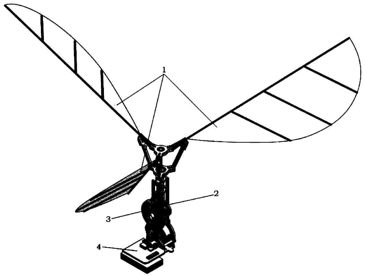
[0051] This embodiment provides the size parameters of a novel drive mechanism for a flapping rotorcraft. In this embodiment, the span of a single aircraft is 130mm, the height of the power unit (not including the airfoil) is 77.4 to 89.4mm, the miniature brushless motor 403 is a 4000kv version AP03 miniature outer rotor brushless motor, and the modulus of all gears is 0.3. Among them, the motor gear 303 has 9 teeth, the double-layer gear 302 has 12 and 36 teeth, the large gear 301 has 70 teeth, the working length of the airfoil rod is 21mm, the working length of the rocker arm 314 is 6mm, and the steering gear model is Pingzheng PZ-15320 Ultra-miniature low-voltage digital steering gear.

[0052] It has been verified by simulation that the novel driving mechanism of the present invention for flapping rotorcraft can realize normal flapping and rotating motion of the wing surface, with a flapping range of about ±35° and a maximum lift of about 38g.


PUM


Abstract

The invention discloses a driving mechanism for a flapping rotor aircraft, and belongs to the technical field of aircraft design. The driving mechanism comprises wings, a fuselage, a transmission device and a power device; the fuselage is of a 3D-printed integrated structure and comprises a motor mounting side panel structure, a gear mounting side panel structure, a sleeve, a sleeve supporting frame, supporting rods, a supporting bridge and a flight control plate platform; the transmission device comprises a large gear, a double-layer gear, a motor gear, a cylindrical sliding rod, a sliding rail, an inner rod, wing mounting frames, wing connecting rods, a sleeve bearing, an inner rod bearing, an inner rod hinge support, a sleeve hinge support, a small bearing, rocker arms and flange bearings; and the power device comprises a micro power supply, a flight control plate, a micro brushless motor and a motor bearing. The complete machine stability is improved, and lift is greatly increased;and airfoils are driven to flap up and down through a sliding rail-sliding rod mode, thus transmission is smoother, and a larger load can be transmitted.

Description

technical field [0001] The invention belongs to the technical field of aircraft design, and in particular relates to a driving mechanism for a flapping rotor aircraft. Background technique [0002] The current unmanned aerial vehicle system is playing an increasingly important role in the civil and military fields. Among various types of unmanned aerial vehicles, especially the micro air vehicle is a research hotspot in the field of international aviation. Researches at home and abroad generally divide micro-aircraft into three types: micro-fixed-wing aircraft, micro-rotor aircraft, and micro-flapping-wing aircraft according to the flight mode. Miniature fixed-wing aircraft has the advantages of fast flight speed and high aerodynamic efficiency, but it cannot hover and has high requirements for take-off and landing conditions. The biggest advantage of micro-rotor aircraft is that it can take off and land vertically and hover, and does not require a large area for take-off a...

Claims


Application Information

Patent Timeline
Patent Type & Authority Applications(China)
IPC IPC(8): B64C33/02
CPCB64C33/02
Inventor 李道春向锦武王子瑜葛奕林
Owner BEIHANG UNIV
Why Eureka
Try Eureka