Transmission device

a transmission device and transmission technology, applied in the field of transmission devices and transmission methods, can solve the problems of increasing the time necessary for accumulation, prolonging the signal delay time, and affecting the transmission ability of low-delay sdh/sonet as an advantage of sdh/sonet, so as to reduce the increase in occupancy ratio, high accommodating efficiency, and the effect of overhead packetization

Inactive Publication Date: 2010-05-06
HITACHI LTD
View PDF9 Cites 6 Cited by
  • Summary
  • Abstract
  • Description
  • Claims
  • Application Information

AI Technical Summary

Benefits of technology

[0010]With the transmission device configured as above, both the high accommodating efficiency (reduction of the increase in the occupancy ratio of the non-payload areas (e.g. ov

Problems solved by technology

However, the aforementioned method increasing the number of frames accumulated before the packetization causes at least a delay corresponding to the number of the accumulated frames, by which the low-delay transmission capability of SDH/SONET as an advantage of SDH/SONET is impaired.
In other words, accumulating a larger number of time-division multiplexed signals for the packetiza

Method used


Image

  • Transmission device
  • Transmission device
  • Transmission device

Examples


Embodiment Construction

[0025]Referring now to the drawings, a description will be given in detail of a preferred embodiment in accordance with the present invention.

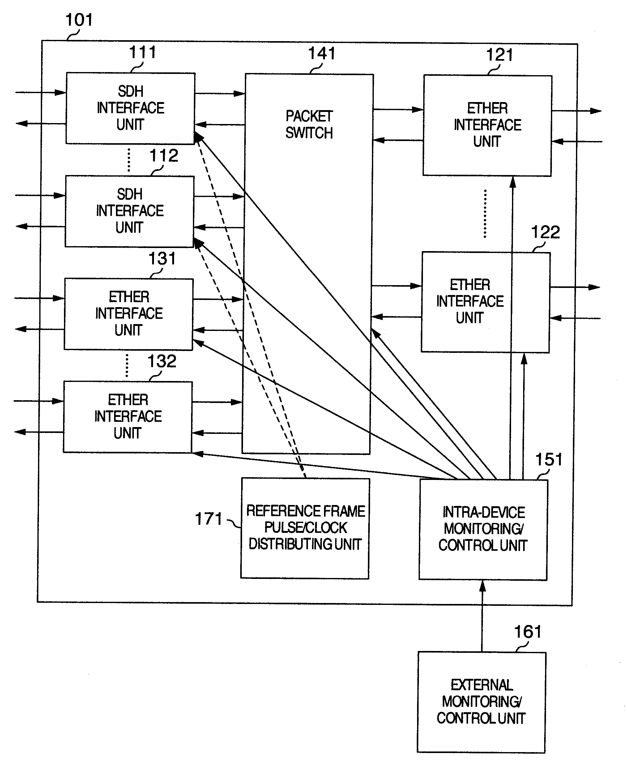
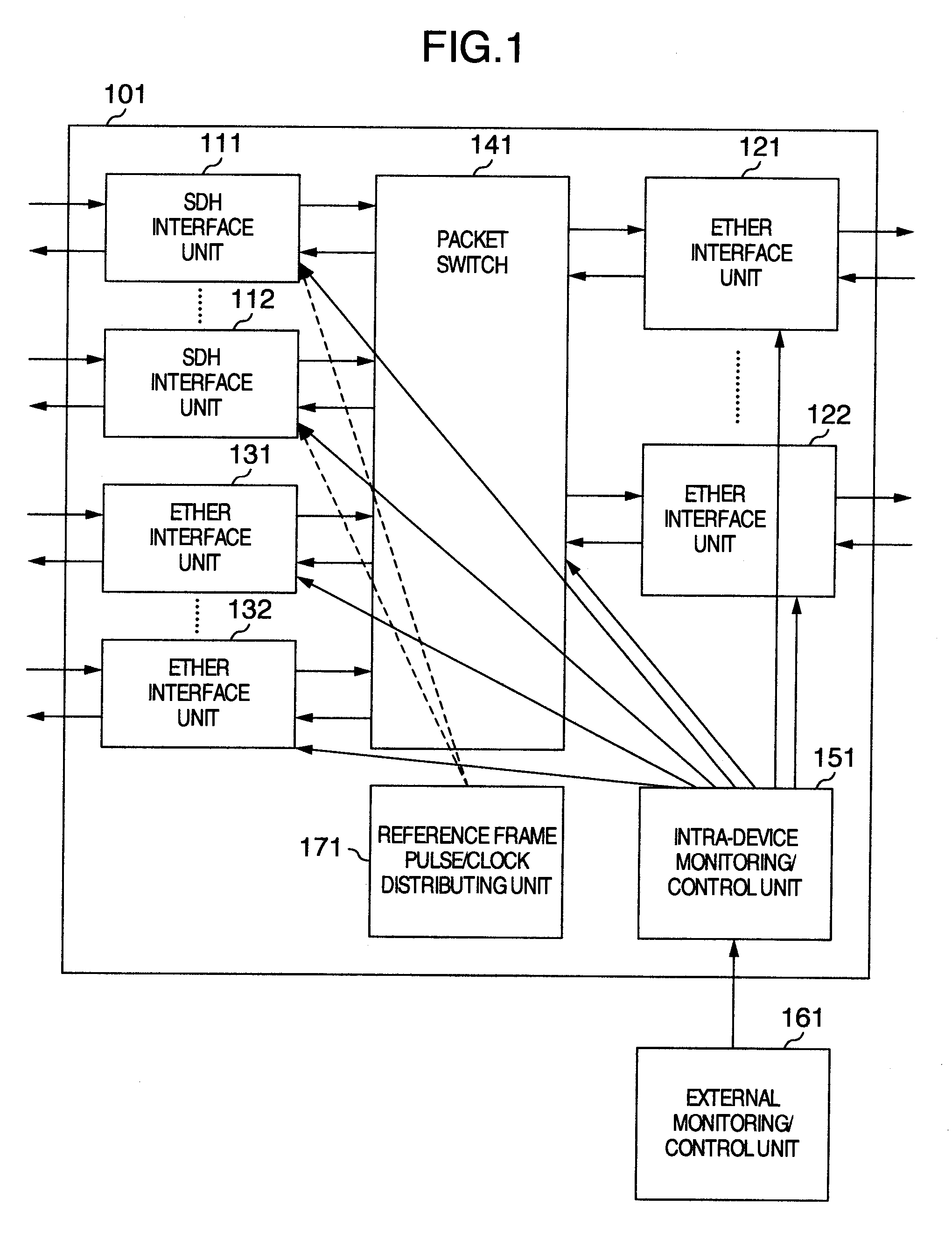
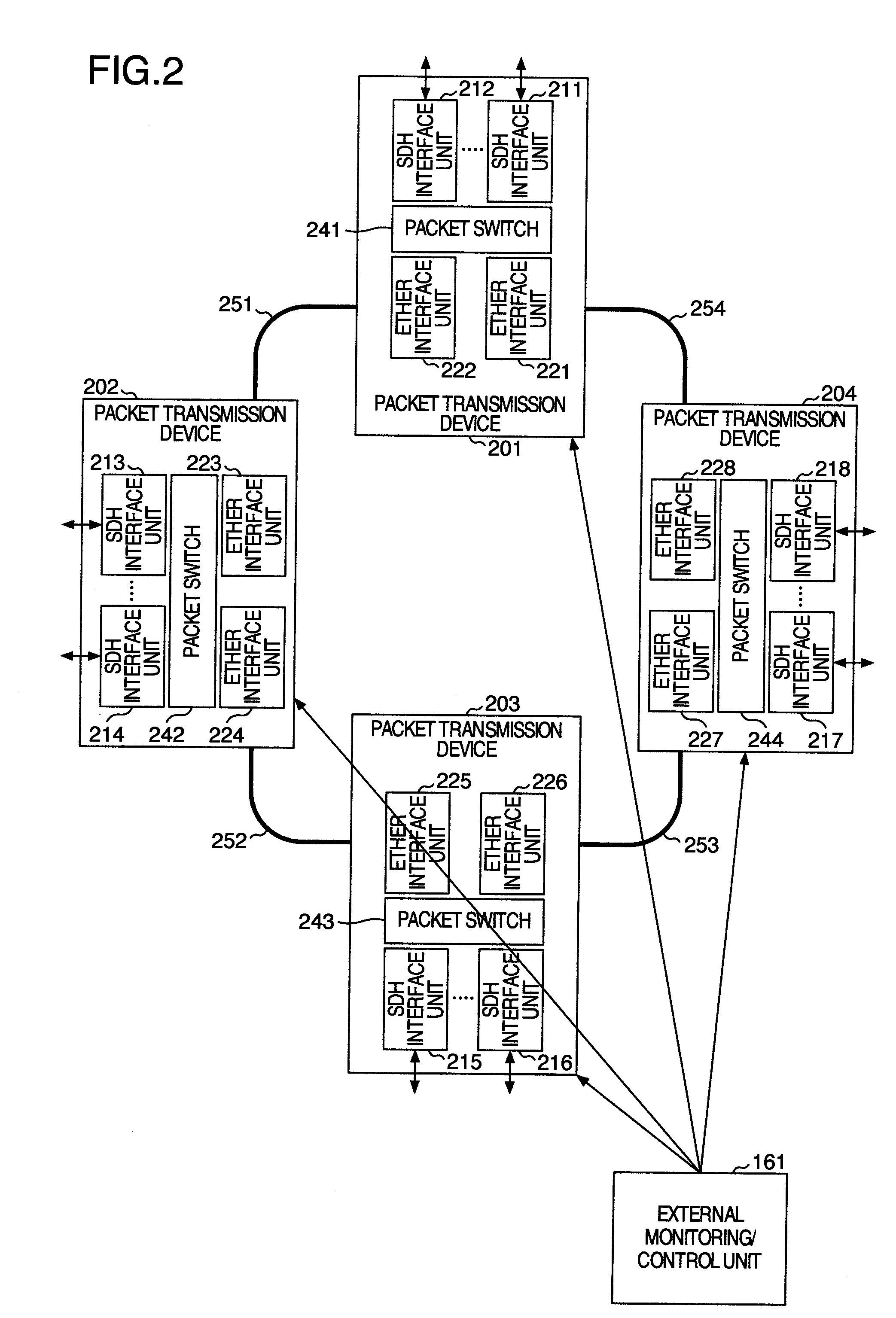
[0026]FIG. 2 is a schematic diagram for explaining a network in which packet transmission devices in accordance with an embodiment of the present invention are connected together in a ring shape. In FIG. 2, an example of a ring configuration including four packet transmission devices 201-204 is shown. The packet transmission devices 201-204 are connected together by connecting their Ethernet interface units 221-228 in the ring shape via optical fiber cables 251-254. The packet transmission devices 201-204 are connected also to external connection devices via SDH (Synchronous Digital Hierarchy) interface units 211-218. In each packet transmission device (201-204), SDH signals sent from an external connection device is accommodated by an SDH interface unit (211-218), converted into T-MPLS (MultiProtocol Label Switching) frames (packets), and the...


PUM


Abstract

A transmission device comprises first interfaces each of which receives time-division multiplexed signals from an external device in units of frames, a switch which is connected with the first interfaces and sets paths of the signals received from the first interface in regard to each packet, and second interfaces each of which is connected with the switch, receives the signals from the first interface via the switch, and transmits the received signals to a different transmission device in units of packets. The first interface selects signals having the same destination from the signals contained in the received frame and stores the selected signals having the same destination in one packet.

Description

INCORPORATION BY REFERENCE[0001]The present application claims priority from Japanese applications JP2008-273721 filed on Oct. 24, 2008, the content of which is hereby incorporated by reference into this application.BACKGROUND OF THE INVENTION[0002]The present invention relates to a transmission device and a transmission method for transmitting signals by accommodating time-division multiplexed signals in signals in a packet format.[0003]Backbone networks of communication carriers are being progressively switched and shifted to full-IP·Ethernet networks in recent years. In such circumstances, already-existing backbone networks employing the time-division multiplexing technology (based on SDH / SONET, for example) and newly emerging backbone networks transmitting information in a packet format (based on IP·Ethernet, for example) are coexisting.[0004]In order to eliminate inefficiency of equipment, maintenance, etc. due to the above coexistence of different types of networks, a lot of s...

Claims


Application Information

Patent Timeline
IPC IPC(8): H04J3/00H04L47/43
CPCH04J3/085H04J3/1611H04L45/50
Inventor SHIBASAKI, MASATOSHIFUKUSHIMA, TAKAOATSUMI, TOSHIYUKINOGI, YOSHIO
Owner HITACHI LTD
Why Eureka
Try Eureka