
Vehicle headlight device

A technology for headlights and vehicles, which is applied in the direction of headlights, vehicle parts, signal devices, etc., can solve the problems of driver's sense of terror and narrowing of the front vision.

Active Publication Date: 2015-05-27
DENSO CORP +2
View PDF7 Cites 5 Cited by
  • Summary
  • Abstract
  • Description
  • Claims
  • Application Information

AI Technical Summary

Problems solved by technology

[0006] However, as disclosed in Patent Document 1, if the low beam is switched to the low beam regardless of whether there is a preceding vehicle or an oncoming vehicle at the corner, the front field of vision may be narrowed, which may give the driver of the own vehicle a sense of terror.

Method used


Image

  • Vehicle headlight device
  • Vehicle headlight device
  • Vehicle headlight device

Examples


Embodiment Construction

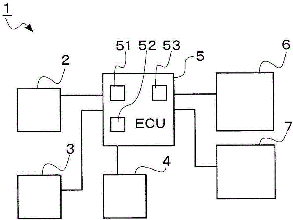
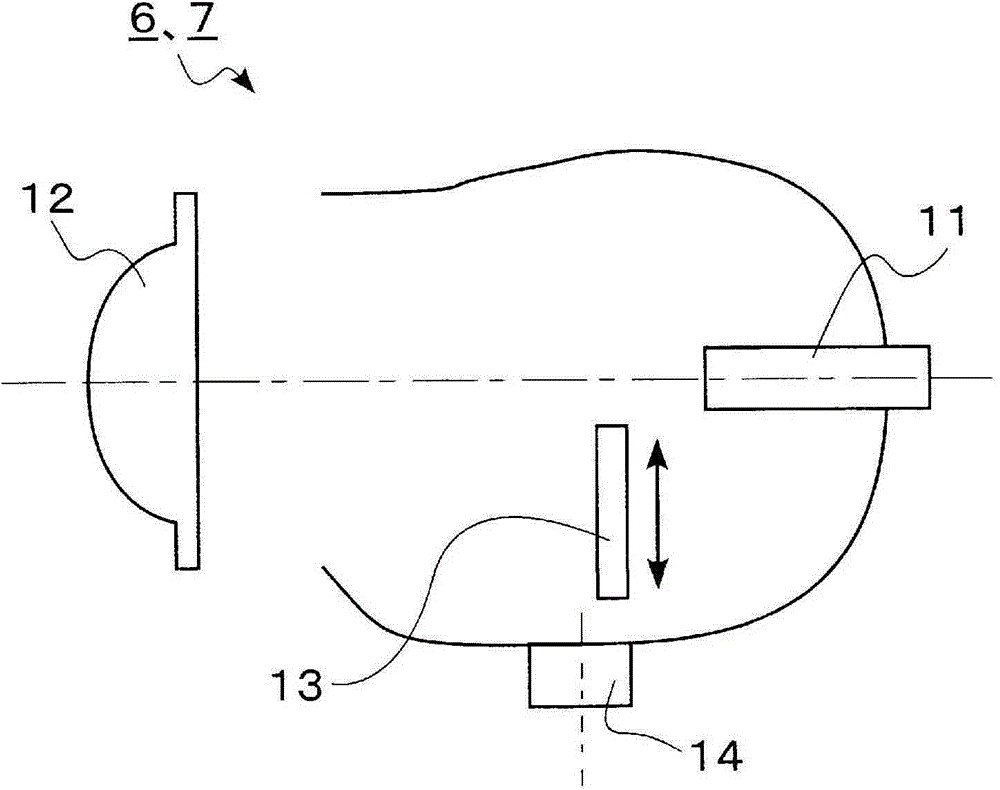
[0016] Below, refer to Figure 1~6 , the vehicle headlamp device according to the embodiment of the present invention will be described. Such as figure 1 As shown, a vehicle headlamp device 1 includes an on-vehicle imaging device 2 , a steering angle sensor 3 , a wheel speed sensor 4 , an ECU (Electronic Control Unit) 5 , and headlamps 6 and 7 .

[0017] The vehicle-mounted photographing device 2 is arranged inside the front window of the vehicle, photographs the front of the vehicle, and sends the data to the ECU 5 . The steering angle sensor 3 is an existing sensor provided for ESC (Electronic Stability Control: Electronic Stability Control, anti-skid device), and is provided in a steering mechanism. The steering angle sensor 3 detects the steering angle of the vehicle, and sends a steering angle signal indicating the detection result to the ECU 5 . The wheel speed sensor 4 is an existing sensor provided for an ABS (Anti-lock Braking System). The wheel speed sensor 4 det...


PUM


Abstract

This vehicle headlight device is provided with: headlights that provide illumination in front of a vehicle; a light distribution pattern switching means that switches the light distribution pattern of the headlights between a plurality of light distribution patterns including at least high beams and low beams; a detection means that detects vehicles ahead, which exist in front of the vehicle; a control means that controls the light distribution pattern switching means on the basis of detection results of the detection means; and a turning radius acquisition means that acquires the turning radius of the vehicle while traveling. In addition, the control means stops the headlights from switching to the high beam light distribution pattern when the turning radius of the vehicle acquired by the turning radius acquisition means is smaller than a prescribed value.

Description

technical field [0001] The present invention relates to a vehicle headlamp device. Background technique [0002] In the past, in order to improve the safety when driving at night, there has been known a high beam variable headlight system ( Adaptive Driving Beam System: Adaptive High Beam System). [0003] Specifically, the variable high beam headlamp system detects the position of the vehicle ahead by image processing information from the on-board camera, and uses a light distribution pattern called intermediate high beam to make the shade follow the vehicle ahead , do not give strong light (glare) to the vehicle in front, ensure the forward vision of the vehicle in a wide range, and easily find pedestrians, etc., wherein the so-called middle high beam refers to covering a part of the irradiation range and illuminating other parts with high beam . [0004] In addition, Patent Document 1 discloses that a visor mechanism provided in the headlight shields a part of the irra...

Claims


Application Information

Patent Timeline
Patent Type & Authority Applications(China)
IPC IPC(8): B60Q1/12B60Q1/14
CPCB60Q1/12B60Q1/143B60Q2300/056B60Q2300/41B60Q2300/122B60Q1/085
Inventor 今枝恒治笠井一望月清隆高垣达也
Owner DENSO CORP
Learn More