An antique wood floor processing machine

A technology for processing machines and wood floors, applied in wood processing appliances, manufacturing tools, forming/shaping machines, etc., can solve the problems of high labor intensity, low production efficiency, waste of resources, etc., and achieve high transmission efficiency, low-speed torque, The effect of high safety factor

Inactive Publication Date: 2017-03-01
盐城鼎恒机械有限公司
View PDF1 Cites 0 Cited by
  • Summary
  • Abstract
  • Description
  • Claims
  • Application Information

AI Technical Summary

Problems solved by technology

Low production efficiency, high labor intensity, and difficult processing of hard wood have seriously restricted the company's ability to increase production capacity and export foreign exchange; on the other hand, due to the particularity of hand-made, some short growth cycles and hard wood are produced Enterprise abandonment, waste of resources
[0003] Although there are existing machines to replace labor, such as the wooden floor processing machine disclosed in the patent application number 201310480801.8, which is named "a new type of antique wood floor processing machine" previously applied by the applicant, there are still the following problems : (1) The multi-cutter coaxial cutting system is used to obtain the required texture effect through the independent swing of three scrapers on a main shaft, but each knife is equipped with an induction device, which is easy to cause the scraper to vibrate when it swings separately. Interference occurs, resulting in jamming and unable to process normally; (2) It is inconvenient to change the tool. Since three tools share one spindle, the entire tool shaft needs to be removed when changing the tool, and each tool combination needs to be replaced. If frequent It is very troublesome to replace the tool in a timely manner, and it is easy to cause the phenomenon that the tool spindle and the motor spindle are not in the same axis, which affects the stability of the transmission

Method used


Image

  • An antique wood floor processing machine
  • An antique wood floor processing machine
  • An antique wood floor processing machine

Examples


Embodiment Construction

[0031] The present invention will be further described below in conjunction with the accompanying drawings and embodiments.

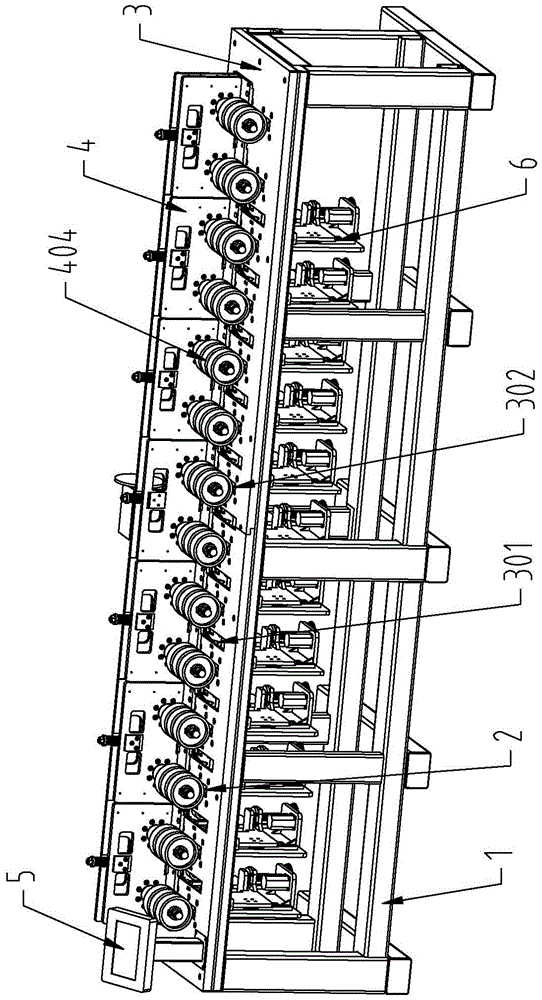
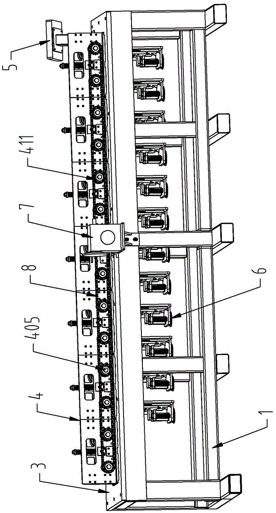
[0032] Such as Figure 1-4Shown: an antique wooden floor processing machine, including a frame 1, on which a worktable 3, a sheet material conveying device 4, a cutting device 6, a floating material device 2 and a touch screen 5 are installed, wherein the sheet material The conveying device 4 is installed on the workbench 3, the cutting device 6 and the floating material device 2 are installed under the workbench 3, and the workbench 3 is provided with a cutting groove 301 corresponding to the cutting device 6 and corresponding to the floating material device 2. Corresponding to the floating material tank 302 , the floating material tank 302 is located directly below the conveying pressing wheel 404 on the sheet material conveying device 4 , and the cutting groove 301 and the floating material tank 302 are arranged at intervals. Specifically, the cutti...


PUM


Abstract

The invention discloses a novel archaistic wood floor processing machine, which comprises a rack (1), wherein the rack (1) is provided with a working platen (3), a plate material conveying device (4), a cutting device (6), a material floating device (2) and a touch display screen (5); the plate material conveying device (4) is installed on the working platen (3); the cutting device (6) and the material floating device (2) are installed below the working platen (3); the working platen (3) is provided with a cutting groove (301) corresponding to the cutting device (6) and a material floating groove (302) corresponding to the material floating device (2); the material floating groove (302) is positioned just below a conveying pinch roller (404) on the plate material conveying device (4); the cutting groove (301) and the material floating groove (302) are arranged at an interval. When scraping milling cutters of the novel archaistic wood floor processing machine are in work, the scraping milling cutters do not mutually interfere and can be conveniently replaced, and the processing machine has the advantages of stable performance, low cost and low maintenance cost due to a modularization design.

Description

technical field [0001] The invention relates to the technical field of design and manufacture of mechanical equipment, in particular to an antique wood floor processing machine with convenient tool change, flexible swing and stable transmission. Background technique [0002] Antique wood flooring is favored by consumers for its naturalness, elegance, and simplicity. At present, antique wood flooring is very popular in Europe, America and Japan. Antique floors in classic moldings. At present, domestic enterprises producing antique wood flooring, especially those exporting to Europe and the United States, use hand-made labor methods, which are labor-intensive and require workers to have a certain technical level. Low production efficiency, high labor intensity, and difficult processing of hard wood have seriously restricted the company's ability to increase production capacity and export foreign exchange; on the other hand, due to the particularity of hand-made, some short gr...

Claims


Application Information

Patent Timeline
Patent Type & Authority Patents(China)
IPC IPC(8): B27M3/04
CPCB27C5/00B27C5/02B27C5/06B27G3/00
Inventor 李青祝张侃楞杨锦虎张沥文
Owner 盐城鼎恒机械有限公司
Why Eureka
Try Eureka