Disc feed machine

A disc feeder and feeder technology, applied in conveyors, rotary conveyors, transportation and packaging, etc., can solve problems such as easy occurrence of safety accidents, external dust entering the reducer, transmission failure, etc.

Inactive Publication Date: 2015-06-03
石传胜
View PDF0 Cites 0 Cited by
  • Summary
  • Abstract
  • Description
  • Claims
  • Application Information

AI Technical Summary

Problems solved by technology

During the working process of the feeder with this traditional structure, it is easy for external dust to enter the transmission part of the reducer and the motor, resulting in transmission failure and safety accidents

Method used


Image

  • Disc feed machine

Examples


Embodiment Construction

[0011] The preferred embodiments of the present invention will be described in detail below in conjunction with the accompanying drawings.

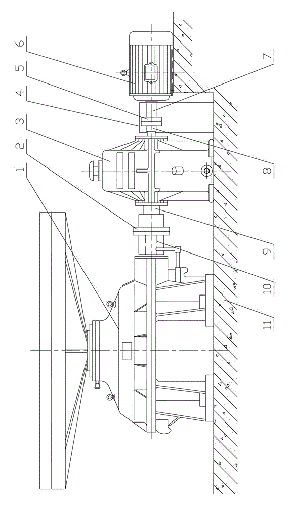
[0012] see figure 1 , the present invention has base 11, and feeder main body 1 is housed on base 11, and the right side of feeder main body 1 is positioned at base 11 and is equipped with reducer 3 and motor 6, and the output shaft 7 of motor 6 and the input shaft of reducer 3 8 is fixedly connected, the output shaft 9 of the reducer 3 is fixedly connected with the rotating shaft 10 of the feeder main body 1; in particular: the output shaft 7 of the motor 6 is fixedly connected with the input shaft 8 of the reducer 3 through a coupling B5, And a safety cover 4 is also installed between the motor 6 and the speed reducer 3, and the safety cover 4 covers the outside of the shaft coupling B5.

[0013] In this embodiment, the output shaft 9 of the speed reducer 3 is fixedly connected with the rotating shaft 10 of the feeder main body 1 throu...


PUM


Abstract

The invention discloses a disc feed machine. The disc feed machine comprises a base. A feed machine body is arranged on the base. A speed reducer and an electric motor are arranged on the portion, located on the base, of the right side of the feed machine body. An output shaft of the electric motor is fixedly connected with an input shaft of the speed reducer. An output shaft of the speed reducer is fixedly connected with a rotating shaft of the feed machine body. The disc feed machine is characterized in that the output shaft of the electric motor is fixedly connected with the input shaft of the speed reducer through a coupler B, and a safety cover is arranged between the electric motor and the speed reducer and covers the coupler B. The safety cover is additionally arranged, it can be ensured that the transmission between the electric motor and the speed reducer is smooth, the transmission failure is prevented, safety accidents can be prevented, and the disc feed machine is mainly used as a feed device in a cement machine.

Description

technical field [0001] The invention relates to the technical field of cement machinery equipment, in particular to a disc feeder. Background technique [0002] At present, the traditional disc feeder has a base, and the main body of the feeder is installed on the base. The right side of the main body of the feeder is located on the base, and a reducer and a motor are installed on the base. The output shaft of the motor is fixedly connected with the input shaft of the reducer. The output shaft of the feeder is fixedly connected with the rotating shaft of the main body of the feeder, and the output shaft of the motor is fixedly connected with the input shaft of the reducer through the coupling B. During the working process of the feeder with this traditional structure, it is easy for external dust to enter the transmission part of the reducer and the motor, resulting in transmission failure and safety accidents. Therefore, it is very necessary to design a disc feeder that ca...

Claims


Application Information

Patent Timeline
IPC IPC(8): B65G29/00
CPCB65G29/00
Inventor 石传胜
Owner 石传胜
Why Eureka
Try Eureka