Fault detection system and method for power transmission line

A transmission line and detection system technology, applied in the direction of fault location, measuring electricity, measuring devices, etc., can solve the problems of high false alarm rate, erection method, susceptibility to line faults in the working environment, and the impact on the daily life of the masses, so as to improve The effect of inspection speed, improvement of processing speed and reliability of judgment

Active Publication Date: 2015-06-03
STATE GRID CORP OF CHINA +1
View PDF8 Cites 18 Cited by
  • Summary
  • Abstract
  • Description
  • Claims
  • Application Information

AI Technical Summary

Problems solved by technology

[0003] At present, my country uses 10KV lines as the last step of high-voltage power transmission. This kind of reference is very common. 10KV lines are used as upper-level power transmission lines with civilian voltages of 220V and 380V. The line routing is relatively complicated, the geographical environment is relatively harsh, and there are line safety At the same time, because the 10KV line is the end of the main high-voltage line, its erection method and working environment have caused the susceptibility of line faults; when the 10KV line fails, its downstream transformer will stop supplying power to users, and this fault will The power outage of the subordinate users in the corresponding transformer station area of ​​the assembly leads to the loss of industrial and agricultural production, which seriously affects the daily life of the masses
However, the currently used line fault detection device has the disadvantages of poor real-time performance, high false alarm rate, and failure to realize communication network integration.

Method used


Image

  • Fault detection system and method for power transmission line
  • Fault detection system and method for power transmission line

Examples


Embodiment Construction

[0021] The present invention will be further described below in conjunction with the accompanying drawings.

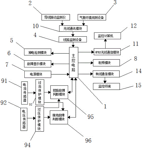
[0022] Such as figure 1 , figure 2 As shown, the transmission line wire temperature online detection system of this embodiment includes a main control circuit 1, a wire vibration monitor 2, a meteorological environment observation device 3, a line monitoring device 4, a power-down detection module 5, a fault display module 6, a power supply Module 7, radio frequency module 8, fault detection module 9, monitoring computer 12, wired communication module 14 and monitoring terminal 15; Conductor vibration detector 2, meteorological environment observation equipment 3 all pass through first wireless communication module 10 and line detection module 4 The input ends are connected, the output end of the line detection device 4 is connected with the input end of the main control circuit 1, the input ends of the power-down detection module 5 and the fault display module 6 ...


PUM


Abstract

The invention relates to a fault detection system and method for a power transmission line. The fault detection system comprises a main control circuit, a conductor vibration monitor, meteorological environment observation equipment, line monitoring equipment, a power failure detection module, a fault display module, a power supply module, a radio-frequency module, a fault detection module and a monitoring computer, wherein the fault detection module comprises a current sensor, a voltage sensor, an overcurrent protection module, an overvoltage protection module, a short-circuit fault judgment module and a grounding fault judgment module. In the fault detection device adopted by the invention, when a short-circuit fault occurs, an electronic switch can be automatically turned off within short time after being turned on; if the short-circuit fault is a transient fault, a current detection device detects no pulse current; if the fault is a permanent fault, the current detection device detects the pulse current, thereby whether the fault is the transient fault or the permanent fault can be judged, a reliable basis is provided for the subsequent fault handling and thus the inspection and maintenance speed of the line can be improved.

Description

technical field [0001] The invention relates to the field of fault detection of high-voltage transmission lines, in particular to a fault detection system and detection method for transmission lines. Background technique [0002] With the rapid development of the national economy, the demand for electricity in all walks of life is increasing, and the requirements for the quality (stability, uninterrupted and accompanying services) of power supply provided by the power supply department are also getting higher and higher. The safety of power grid operation away from high-voltage transmission lines is particularly important. [0003] At present, my country uses 10KV lines as the last step of high-voltage power transmission. This kind of reference is very common. 10KV lines are used as upper-level power transmission lines with civilian voltages of 220V and 380V. The line routing is relatively complicated, the geographical environment is relatively harsh, and there are line safe...

Claims


Application Information

Patent Timeline
Patent Type & Authority Applications(China)
IPC IPC(8): G01D21/02G01R31/02G01R31/08
Inventor 操礼峰薛兵周志黔黄伟
Owner STATE GRID CORP OF CHINA
Why Eureka
Try Eureka