
Image correction method and system

An image correction and correction coefficient technology, applied in the image field, can solve the problems of time-consuming acquisition, calculation, and low accuracy of correction coefficients, and achieve the effects of ensuring accuracy, simplifying generation steps and working time

Active Publication Date: 2018-09-11
SHENZHEN YIHUA COMP +2
View PDF4 Cites 0 Cited by
  • Summary
  • Abstract
  • Description
  • Claims
  • Application Information

AI Technical Summary

Problems solved by technology

[0003] The purpose of the embodiments of the present invention is to provide an image correction method and system, which aims to solve the problem of low accuracy of the correction coefficients caused by the correction coefficients formed by relying on the image sensor for image data acquisition in the prior art, and the need for time-consuming acquisition, calculation problem

Method used


Image

  • Image correction method and system
  • Image correction method and system
  • Image correction method and system

Examples


Embodiment 1

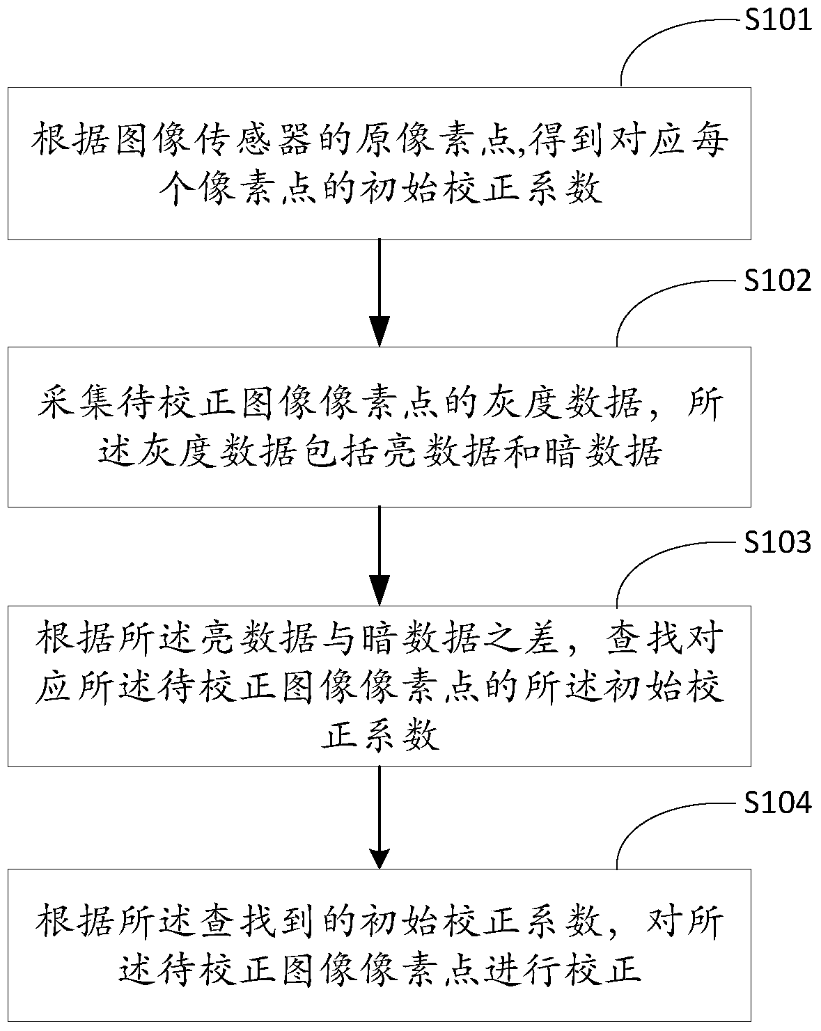
[0024] figure 1 A flow chart of the image correction method provided by the embodiment of the present invention is shown. Such as figure 1 As shown, the embodiment of the present invention provides an image correction method, the method includes the following steps:

[0025] In step S101, an initial correction coefficient corresponding to each pixel is obtained according to the original pixel of the image sensor.

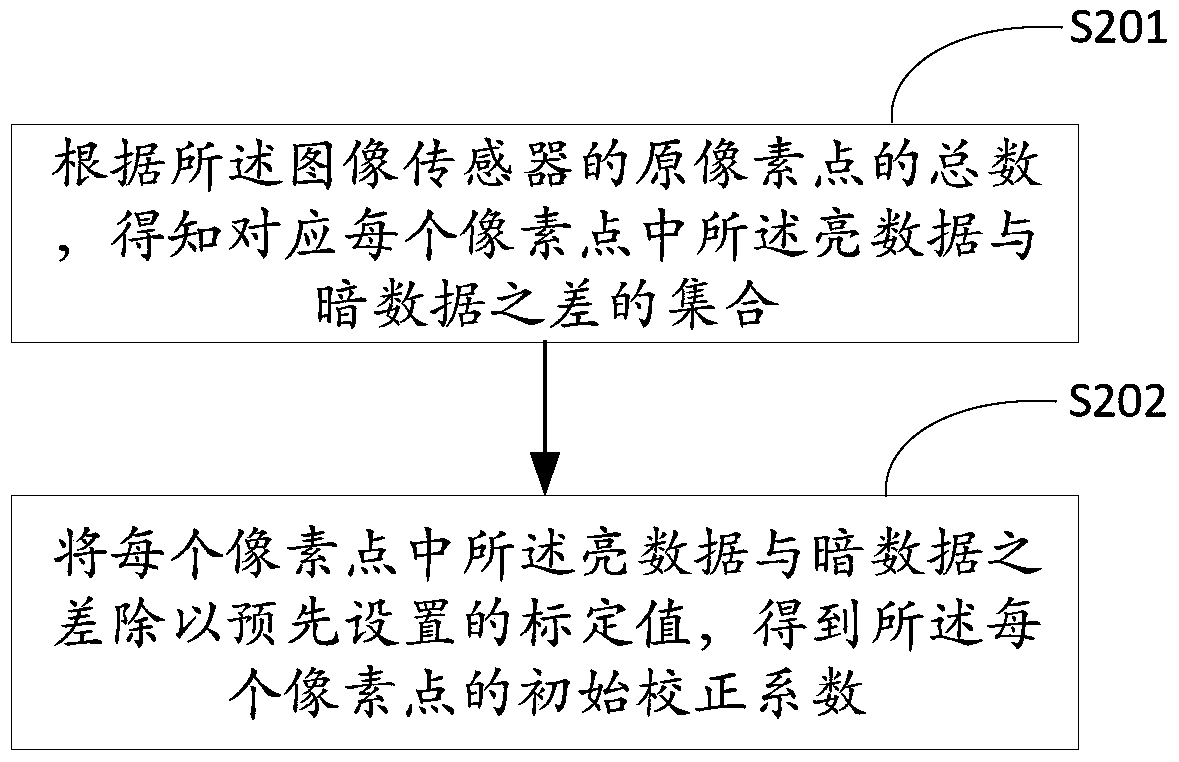
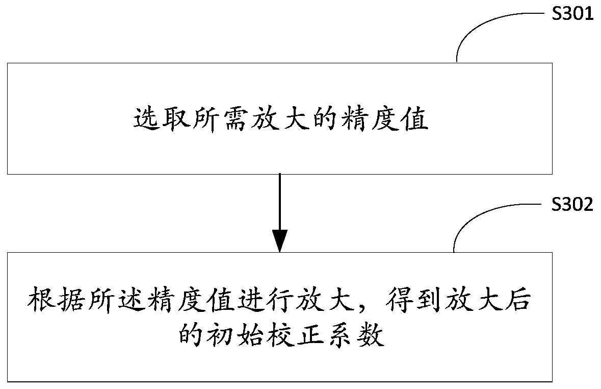
[0026] In this embodiment, a 2D image in which brightness information is usually recorded is called a brightness (grayscale) image. If it is a grayscale image (8-bit grayscale image), its pixel value is its grayscale value. The grayscale value refers to the color depth of the middle point of the black and white image, generally ranging from 0 to 255, and white is 255 and 0 for black. When the image sensor is uniformly illuminated, the video signal amplitudes output by each photosensitive element should be exactly the same, but due to the influence of many factor...

Embodiment 2

[0057] Figure 5 The structural diagram of the image correction system provided by the embodiment of the present invention, for the convenience of description, only shows the part related to the embodiment of the present invention, the image correction system provided by the embodiment of the present invention includes: an initial correction coefficient calculation unit 51, an acquisition Unit 52, search unit 53 and correction unit 54, wherein:

[0058] The initial correction coefficient calculation unit 51 is used to obtain the initial correction coefficient corresponding to each pixel point according to the original pixel point of the image sensor; the acquisition unit 52 is used to collect the grayscale data of the pixel point of the image to be corrected, and the grayscale data Including bright data and dark data; search unit 53, for searching the initial correction coefficient corresponding to the image pixel to be corrected according to the difference between the bright ...


PUM


Abstract

The invention relates to an image correcting method and system. The method comprises the following steps: according to raw pixels of an image sensor, obtaining an initial correcting coefficient corresponding to each pixel; acquiring the gray data of pixels of an image to be corrected, wherein the gray data comprises bright data and dark data; according to a difference value between the bright data and the dark data, searching the initial correcting coefficient of the pixel of the image to be corrected; according to the searched initial correcting coefficient, correcting the pixel of the image to be corrected. Through the utilization of the image sensor, the initial correcting coefficient is obtained; during correcting, only addressing and searching of the corresponding initial correcting coefficient according to the pixel data acquired according to the image to be corrected are needed without obtaining the image data through actual acquisition, so that the correction can be performed through the complete dependency on the characteristic of the image sensor, the precision of the corrected coefficient is ensured, the generating steps of the corrected coefficient is simplified, and the operating time is shortened.

Description

technical field [0001] The invention belongs to the field of images, in particular to an image correction method and system. Background technique [0002] The image sensor is a basic device for modern visual information acquisition. It converts the spatially distributed light intensity information incident on the photosensitive surface into a video signal output in time sequence, so that the image information of the object can be reproduced. In an ideal situation, when the image sensor is uniformly illuminated, the video signal amplitude output by each photosensitive element should be exactly the same, but in fact, due to many factors such as the process level of the device, 1 / f noise, optical system and charge transfer efficiency, etc. The influence of non-uniformity caused the problem of non-uniformity, so that under the same irradiance, the responsivity of each photosensitive element cannot be completely consistent, or even have a large difference. The non-uniformity of t...

Claims


Application Information

Patent Timeline
Patent Type & Authority Patents(China)
IPC IPC(8): G06T5/00
Inventor 周艳玲
Owner SHENZHEN YIHUA COMP
Learn More