Eureka AIR delivers breakthrough ideas for toughest innovation challenges, trusted by R&D personnel around the world.

Mounting element for wiring apparatus and wiring equipment using same

A technology for wiring devices and installing components, which is applied to parts of connecting devices, electrical components, coupling devices, etc., can solve problems such as deformation and achieve the effect of suppressing separation

Inactive Publication Date: 2015-06-03
PANASONIC INTELLECTUAL PROPERTY MANAGEMENT CO LTD
View PDF9 Cites 3 Cited by
  • Summary
  • Abstract
  • Description
  • Claims
  • Application Information

AI Technical Summary

Problems solved by technology

There is a possibility that the force applied from the electric wires to the wiring device may cause deformation of the portion where the first frame body and the second frame body are joined to each other in the direction in which the first frame body and the second frame body are separated.

Method used


Image

  • Mounting element for wiring apparatus and wiring equipment using same
  • Mounting element for wiring apparatus and wiring equipment using same
  • Mounting element for wiring apparatus and wiring equipment using same

Examples


Embodiment Construction

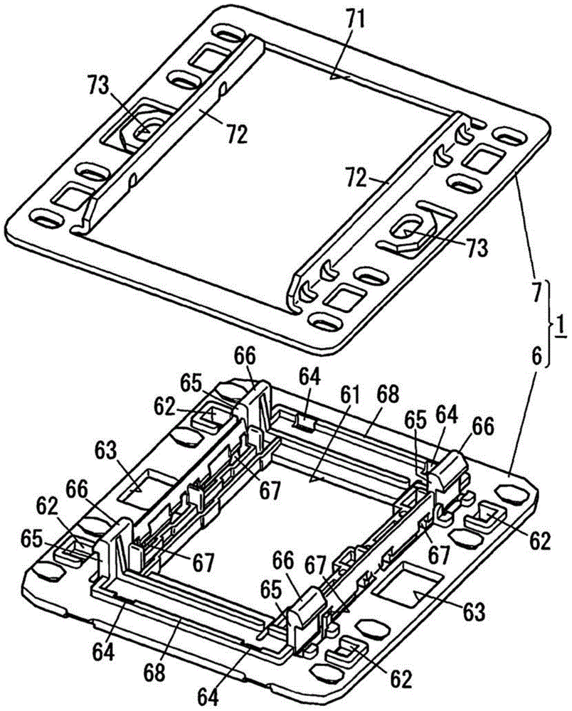
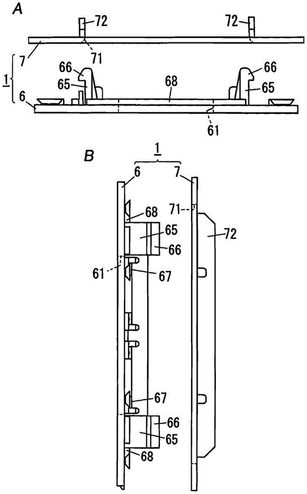
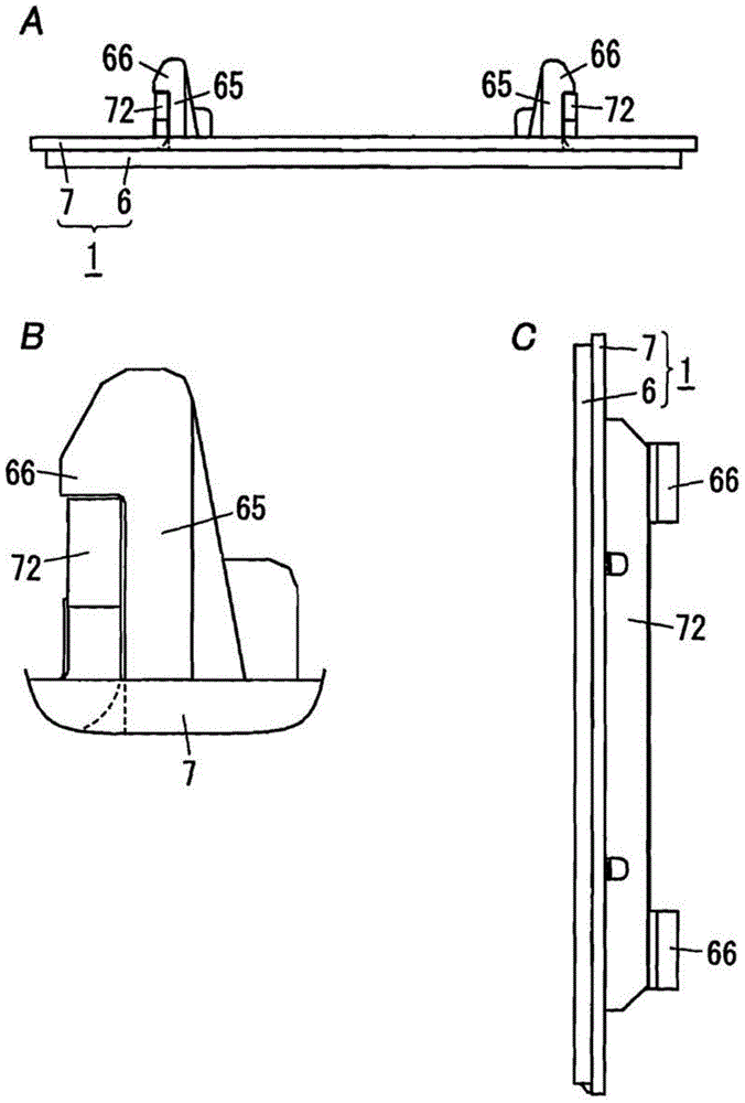
[0013] The following reference is made to an embodiment of a wiring device according to the invention comprising a mounting element for a wiring arrangement Figure 1 to Figure 5 instruction of. In the following descriptions, the up, down, left, and right directions are represented by Figure 4 The up, down, left and right directions in A are defined, and the front and rear sides are respectively in Figure 4 B is shown as left and right.

[0014] Such as Figure 5 As shown, the wiring device 10 according to this embodiment includes a switch 2 (wiring device), a mounting member 1 for wiring device, and a decorative plate 3 attached to the front surface of the mounting member 1 for wiring device. It is noted that the mounting element 1 for the wiring device is only referred to as mounting element 1 in the following. Furthermore, the wiring device 10 includes a backside plate 8 attached to the rear surface of the mounting element 1 . Note that the wiring device 10 shown in ...


PUM


Abstract

The invention provides a mounting element for a wiring apparatus, and wiring equipment using the same. The mounting element can prevent a mounting frame from being separated from a mounting plate. The mounting element for a wiring apparatus includes a metal mounting plate and a mounting frame, wherein the metal mounting plate is configured to be fixed to a building material, and the mounting frame, made from resin, is configured to be attached to the mounting plate. The mounting plate includes a rectangular or square opening part and two protruding members, wherein a switch is arranged in the opening part, and the two protruding members respectively protrude backwards from edge parts, corresponding to the periphery of the opening part, at least on two sides of the opening part. The mounting frame includes a maintaining hole for maintaining the switch, and four protruding parts that protrude from, corresponding to the two protruding members, the rear surface of the mounting frame and that are configured to be connected to the rear edges of the corresponding protruding members. The mounting frame is configured in a way that the corresponding protruding parts fit the opening part from the front side of the mounting plate and are attached to the mounting plate when being connected with the corresponding protruding members.

Description

technical field [0001] The present invention relates to a mounting element for a wiring device and a wiring device using the same, more particularly, to a mounting element for a wiring device for installing a wiring device in building materials, and using the mounting Wiring equipment for components. Background technique [0002] In the past, there has been provided a resin-made mounting frame for a wiring device, which includes: a first frame body (device-side frame body) made of resin and to which a wiring device is attached; A frame body is embedded and fixed to a second frame body (building surface side frame body) of a building surface or the like (for example, see JP2-60417U (hereinafter referred to as Document 1)). [0003] The first frame body and the second frame body disclosed in Document 1 include a frame body locking portion. The frame body locking portion of the first frame body holding the wiring device is engaged with the frame body locking portion of the se...

Claims


Application Information

Patent Timeline
IPC IPC(8): H01H9/02H01R13/502
CPCH01H9/02H01H9/287
Inventor 氏原秀哲
Owner PANASONIC INTELLECTUAL PROPERTY MANAGEMENT CO LTD
Why Eureka
Eureka Blog
Learn More