
Spring-elastic measuring element comprising a flat connecting element that can be welded

A technology for measuring components and connecting components, which is applied in the measurement of fluid pressure through mechanical components, fluid pressure measurement of elastic deformation gauge, welding/welding/cutting items, etc., and can solve the problem of not being able to be replaced immediately, the strength of spring-type elastic measuring components and Adverse effects of corrosion resistance, welding work hindrance, etc., achieve high welding speed, improve mechanical and technical characteristics, and suppress the effect of separation

Inactive Publication Date: 2008-12-10
奥托拉道
View PDF5 Cites 2 Cited by
  • Summary
  • Abstract
  • Description
  • Claims
  • Application Information

AI Technical Summary

Problems solved by technology

Since the measuring springs of the different measuring ranges have different dimensions, large gaps cannot be avoided for this purpose, which prevents perfect gas-tight mechanical welding without wire supply
Furthermore, it should be emphasized that due to the high heat penetration for welding the measuring cell to the base body, the resulting oxide layer penetrates into the weld seam zone as far as the measuring system, wherein otherwise insignificant heat penetration results in structures in the heat-affected zone change, the strength and corrosion resistance of the spring-loaded elastic measuring cell are therefore adversely affected
Formation of blisters and cracks as well as material segregation are also observed in known welding methods, which lead to corrosion and nucleation of cracks
In addition, manual welding must be carried out. Due to the different material thicknesses, this work can only be carried out by experienced manual welding hands. For this reason, certain work experience must be used. Generally, other colleagues cannot be replaced immediately. Serious hindrance to welding work

Method used


Image

  • Spring-elastic measuring element comprising a flat connecting element that can be welded
  • Spring-elastic measuring element comprising a flat connecting element that can be welded
  • Spring-elastic measuring element comprising a flat connecting element that can be welded

Examples


Embodiment Construction

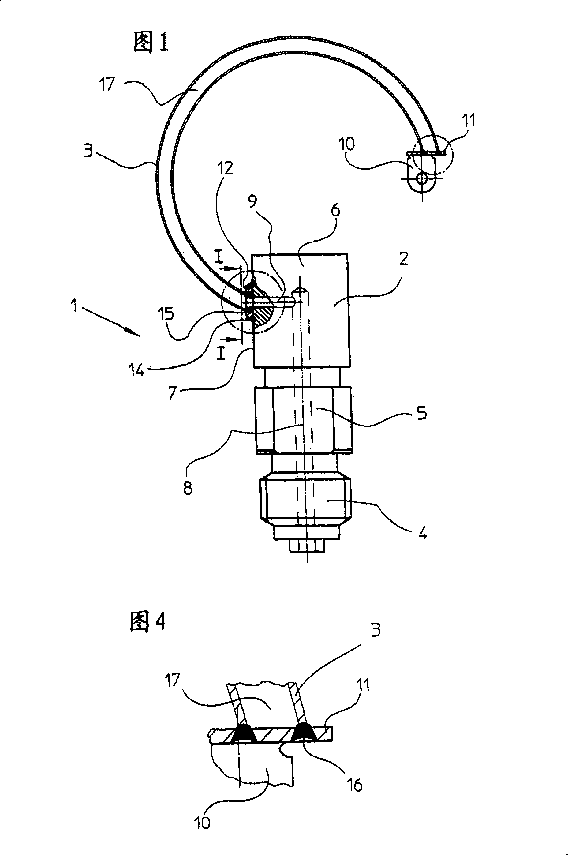
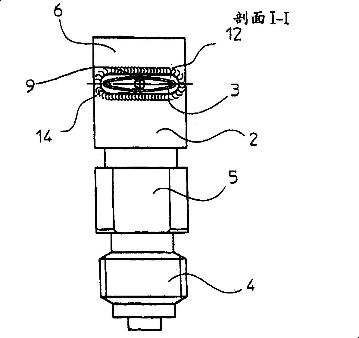
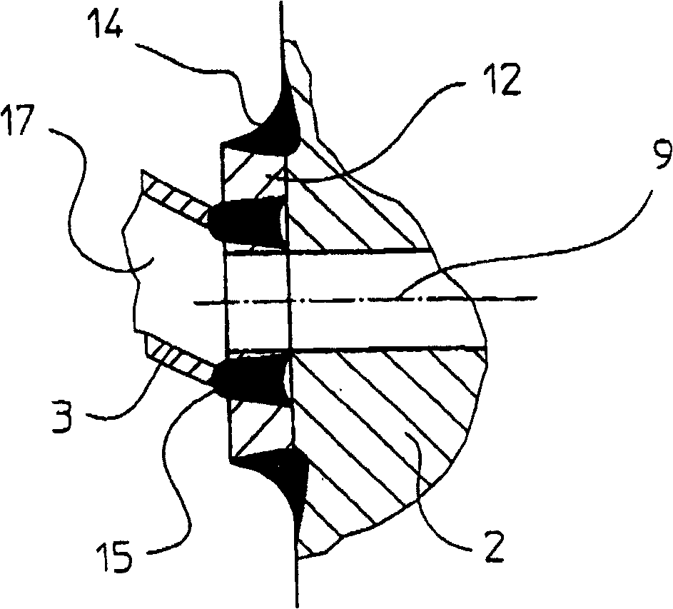
[0018] FIG. 1 shows a spring-loaded elastic measuring element 1 according to the invention, which consists of a base body 2 , a measuring tube 3 and a measuring device, not shown. The base body 2 is formed from a cuboid, which includes a screw connection 4 formed on one side, a middle part 5 and a top part 6 , which has at least one flat surface 7 . In the illustrated embodiment, the base body is of square cross-section. A longitudinal bore 8 is provided in the axial direction of the base body 2 , protruding straight into the top part 6 , which opens into the plane 7 via a transverse bore 9 .

[0019] The measuring tube 3 is arc-shaped and connected to the base body 2 at one end and to a connecting arm 10 at the other end. A first connecting element 11 is arranged between the connecting arm 10 and the measuring tube 3 , and a second connecting element 12 is arranged between the base body 2 and the measuring tube 3 , the connecting elements 11 , 12 have almost the same walls a...


PUM


Abstract

The invention relates to a spring-elastic measuring element ( 1 ) for thermometers, pressure switches or manometers consisting of an arc-shaped measuring tube ( 3 ), a base body ( 2 ) and a connecting element ( 10 ) for the measuring mechanism. The aim of the invention is to achieve the fully automated welding of the thermally influenced zone and to improve the latter. To achieve this, the connections between the measuring tube ( 3 ) and the base body ( 2 ) and the measuring tube and the connecting element ( 10 ) are obtained using connecting elements ( 11, 12 ) that can be welded. This allows the risk of contamination of the measuring system to be eliminated to a great extent and reduces the formation of corrosion and vibration cracks by the use of a small thermally influenced zone. A connecting element ( 11, 12 ) can also be produced as one-piece with the measuring tube ( 3 ) by expanding or creating a bead on the latter. The welded joint can be achieved by laser welding or electron-beam welding and the invention permits the welding of chrome-nickel steel to bronze.

Description

technical field [0001] The invention relates to a spring-type elastic measuring element, especially for thermometers, pressure switches or pressure gauges, comprising a curved or helical measuring tube, which is connected at one end to a base and at the other end to a measuring device The joint element connection is especially welded. Background technique [0002] For pressure- or temperature-sensitive measuring instruments, an elastic spring element made of thin-walled material can be used which deforms under the prevailing pressure. For this reason, the measuring element is generally formed in an arc shape and one end is connected to a solid base, and the other end is connected to the measuring device through a connecting rod, so that through the deformation that occurs, a small force is applied to the measuring device through the connecting rod. This thrust generated during the rotary movement is transmitted via the measuring device to the indicating device. In this cas...

Claims


Application Information

Patent Timeline
IPC IPC(8): G01L7/04G01K5/36B23K33/00B23K15/00B23K26/32
CPCB23K15/0006G01K5/36G01L7/041B23K26/32B23K2103/08B23K2103/18B23K2103/22B23K2103/50
Inventor 奥托·拉道
Owner 奥托拉道
Features
  • Generate Ideas
  • Intellectual Property
  • Life Sciences
  • Materials
  • Tech Scout
  • Unparalleled Data Quality
  • Higher Quality Content
  • 60% Fewer Hallucinations
Learn More