All-position automatic welding method for pipeline circumferential weld

An automatic welding, all-position technology, applied in welding equipment, tubular objects, arc welding equipment, etc., can solve the problems of high requirements for welders' operating skills, high cost of welding equipment, poor performance of welding joints, etc., to shorten the construction period, reduce The effect of porosity sensitivity and less welding material

Active Publication Date: 2014-05-21
BC P INC CHINA NAT PETROLEUM CORP +1
View PDF6 Cites 25 Cited by
  • Summary
  • Abstract
  • Description
  • Claims
  • Application Information

AI Technical Summary

Problems solved by technology

This welding method overcomes the low welding efficiency, large consumption of welding materials, many weld defects, poor performance of welded joints and high requirements for welders' operation skills in the prior art by designing the groove type and selecting the welding process of root welding and filling cover. Or the disadvantages of expensive welding equipment, difficult operation and maintenance, etc.

Method used


Image

  • All-position automatic welding method for pipeline circumferential weld
  • All-position automatic welding method for pipeline circumferential weld
  • All-position automatic welding method for pipeline circumferential weld

Examples


Embodiment 1

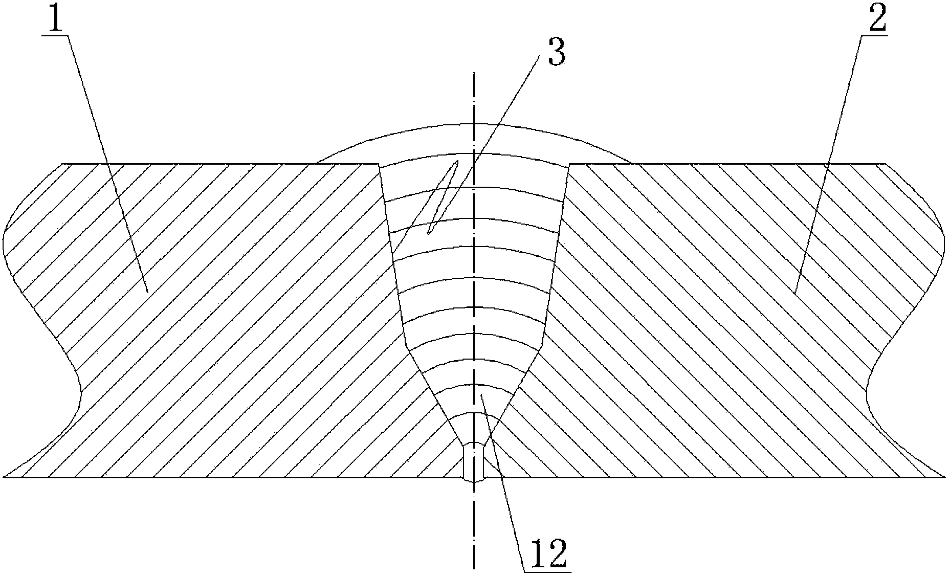
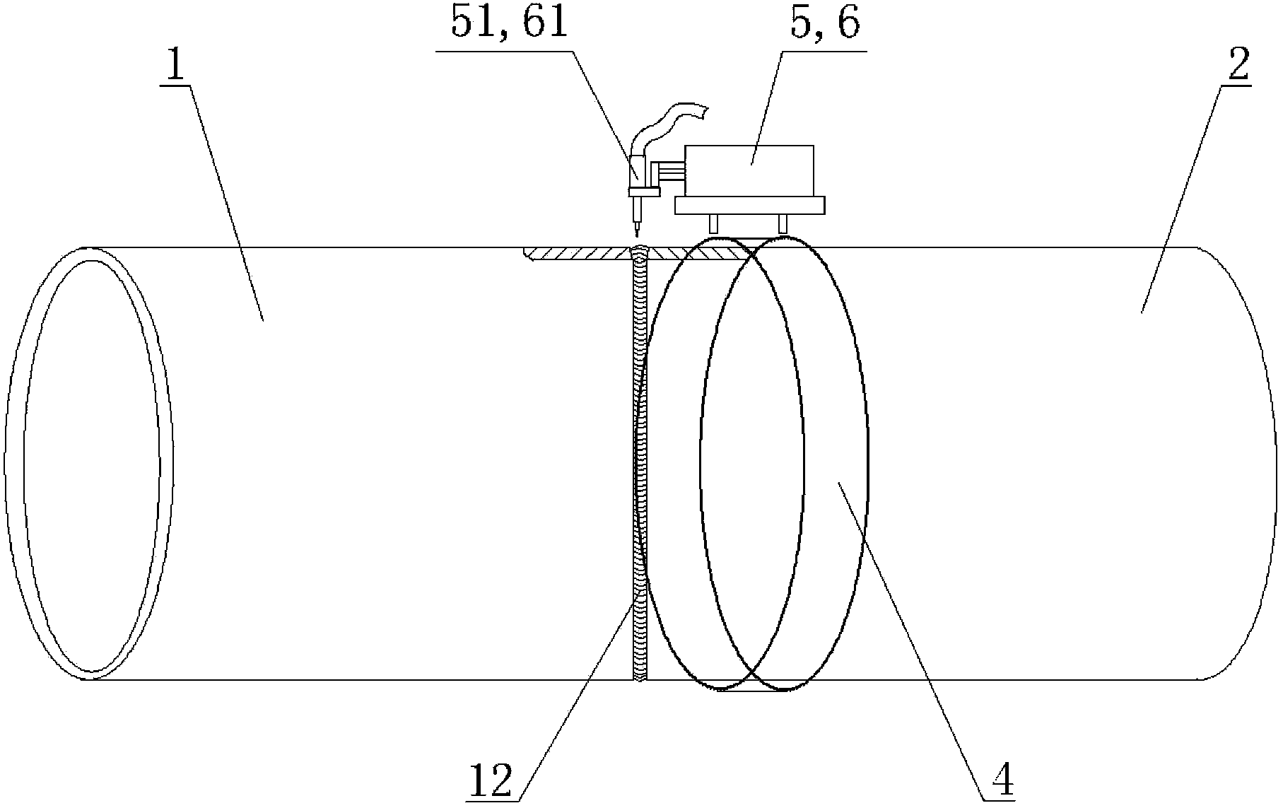
[0051] This embodiment provides an all-position automatic welding method for pipeline girth welds, see figure 1 and figure 2 , the method includes: single torch cold metal transfer (Cold Metal Transfer, abbreviated as CMT) all-position root welding and double-torch all-position automatic heat welding, filling and capping welding.

[0052] The specific steps of the all-position automatic welding method of the pipeline girth weld are:

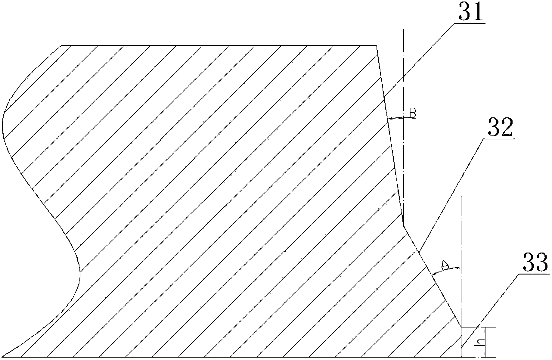
[0053] S1, process the welding end of the first steel pipe 1 and the second steel pipe 2 to be welded into a groove end face 3, the shape of the groove end face is a double V-shaped composite groove, and the groove end face 3 includes the outer wall of the steel pipe to the inner wall of the steel pipe An upslope surface 31 , a downslope surface 32 and a blunt edge 33 are provided in sequence. Preferably, the inclination angle B of the upper broken surface 31 is 5° to 15°, that is, the angle B between the upper broken surface 31 and the vertic...

Embodiment 2

[0073] An embodiment of the present invention provides an all-position automatic welding method for a pipeline girth weld, which is described by taking Φ508 mm×14.3 mm X65 steel grade submarine pipeline girth weld welding as an example. According to APIStandard 1104-2005 "Steel Pipeline Welding and Acceptance" standard, the welding quality acceptance of the girth weld is carried out.

[0074] 1. Pipe end bevel processing

[0075] During the manufacturing process of the Φ508mm×14.3mm X65 steel pipe, the pipe factory processes grooves on both ends of the first steel pipe 1 and the second steel pipe 2. The groove type is double V-shaped composite groove 12, and the angle A of the lower broken surface 32 is 30°, 31 angle B of the upslope surface is 9°, the inflection point C of the downslope surface and the upslope surface transitions smoothly, the distance from the inflection point C to the inner wall of the steel pipe is 7.5mm, the distance from the inflection point C to the out...

Embodiment 3

[0102]The embodiment of the present invention provides an all-position automatic welding method for pipeline girth welds. The girth weld welding of Φ1219mm×22.0mm X80 steel grade land long-distance pipeline is taken as an example to illustrate this embodiment. According to API Standard 1104-2005 "Steel Pipeline Welding and Acceptance" and Q / SY GJX 0110-2007 "Technical Specifications for Line Welding of the Second West-East Gas Pipeline Project", the welding quality acceptance of the girth weld is carried out.

[0103] 1. Pipe end bevel processing

[0104] During the manufacturing process of Φ1219mm×22.0mm X80 steel pipe, the pipe factory processes the groove surface on both ends of the first steel pipe 1 and the second steel pipe 2. °, the angle B of the upslope surface is 9°, the inflection point C of the downslope surface and the upslope surface transitions smoothly, the distance from the inflection point C to the inner wall of the steel pipe is 7.5mm, the distance from the ...


PUM

PropertyMeasurementUnit
diameteraaaaaaaaaa
lengthaaaaaaaaaa
tensile strengthaaaaaaaaaa

Abstract

The invention discloses an all-position automatic welding method for a pipeline circumferential weld and belongs to the technical field of pipeline circumferential weld welding. The method includes the following steps that firstly, steel pipes needing welding are machined to be provided with groove end faces; secondly, welding technology parameters are typed in a controller program according to the preset welding technology; thirdly, the two welded steel pipes are assembled; fourthly, one of the steel pipes is provided with a welding rail; fifthly, the welding ends of the two steel pipes are preheated before welding; sixthly, a single welding torch is used for performing root welding on grooves; seventhly, a double welding torch is used for performing hot welding, filling welding and cosmetic welding on the grooves. According to the all-position automatic welding method for the pipeline circumferential weld, due to the fact that the groove type is designed, the root welding technology, the filling welding technology and the cosmetic welding technology are adopted, the defects that in the prior art, the welding efficiency is low, a large number of welding materials are consumed, a large number of weld defects exist, the welding joint performance is poor, and the requirement for the operating skills of welders is high; or welding equipment is high in cost, and operating and maintaining are difficult are overcome.

Description

technical field [0001] The invention relates to the technical field of pipeline girth weld welding, in particular to an all-position automatic welding method for pipeline girth welds. Specifically, it is a welding method based on CMT (Cold Metal transfer, cold metal transition) root welding, double welding torch filling cover surface, large diameter, large wall thickness, high steel grade long-distance pipeline all-position automatic external welding . Background technique [0002] Large-diameter, high-pressure long-distance pipelines are used more and more in the field of oil and gas transportation, and the requirements for welding technology between pipelines are also getting higher and higher. It has become a symbol of technological progress in pipeline construction. Pipeline girth weld welding is an important part of pipeline construction. The welding quality of girth weld directly affects the safety of pipeline service, and the construction period of pipeline construc...

Claims


Application Information

Patent Timeline
Patent Type & Authority Applications(China)
IPC IPC(8): B23K9/028B23K9/16B23K9/235B23K33/00
CPCB23K9/0282B23K9/164B23K9/235B23K33/00B23K2101/06
Inventor 何小东张雪琴王月霞朱丽霞仝珂刘养勤蔺卫平宋娟
Owner BC P INC CHINA NAT PETROLEUM CORP
Why Eureka
Try Eureka