
Laser-arc hybrid welding method of light sheet T type joint

A hybrid welding and arc technology, used in laser welding equipment, welding equipment, metal processing equipment, etc., can solve the problems of unsmooth weld toe transition and the porosity at the root of the weld cannot be eliminated, and achieve uniform and smooth transition, great economy and technology. Significance, Effect of Solving Stomatal Problems

Inactive Publication Date: 2009-07-08
BEIJING UNIV OF TECH
View PDF0 Cites 25 Cited by
  • Summary
  • Abstract
  • Description
  • Claims
  • Application Information

AI Technical Summary

Problems solved by technology

Solve the structural limitations of T-joint dual-beam welding symmetrically from both sides of the rib plate and when a single laser is used to penetrate through the back plate, the transition of the weld toe at the joint between the rib plate and the bottom plate is not smooth and the pores at the root of the weld cannot Eliminates problems while increasing welding efficiency and reducing weld assembly clearance requirements

Method used


Image

  • Laser-arc hybrid welding method of light sheet T type joint
  • Laser-arc hybrid welding method of light sheet T type joint
  • Laser-arc hybrid welding method of light sheet T type joint

Examples


Embodiment 1

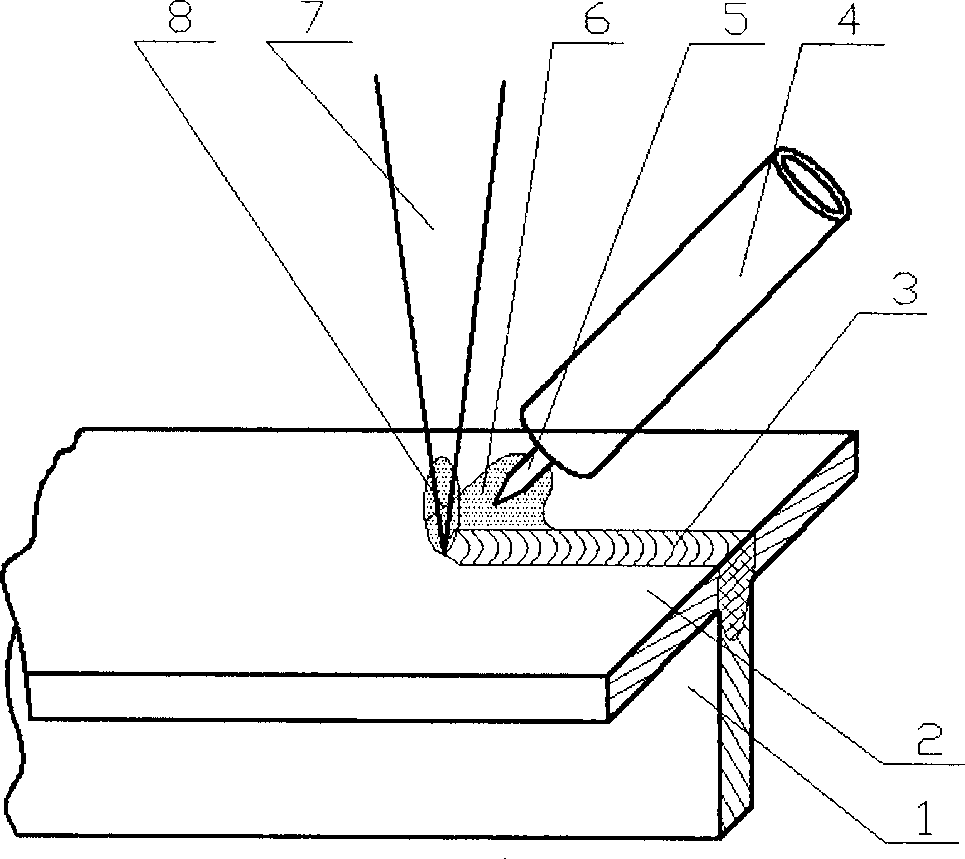
[0020] For the implementation of this embodiment, refer to the attached figure 2 , this embodiment uses CO 2 The laser-TIG arc composite heat source realizes welding from the top surface of the T-shaped joint bottom plate 2, wherein the laser beam 7 is vertically incident from the top surface of the bottom plate 2, and the TIG arc 6 is arranged behind the laser beam 7 paraxially relative to the laser beam 7, and the arc 6 and The included angle of the top surface of the bottom plate is 45°, the composite heat source composed of laser beam 7 and electric arc 6 acts on the top of the rib plate 1, and deep penetration welding is completed from the side of the bottom plate 2 of the T-joint. During welding, the laser beam 7, the arc 6 and the rib 1 are arranged in one plane.

[0021] Among them, the rib plate 1 and the bottom plate 2 are stainless steel plates with a thickness of 2 mm, the laser used is a DC035 SlabCO2 laser, and the TIG power supply is directly connected to DC. ...

Embodiment 2

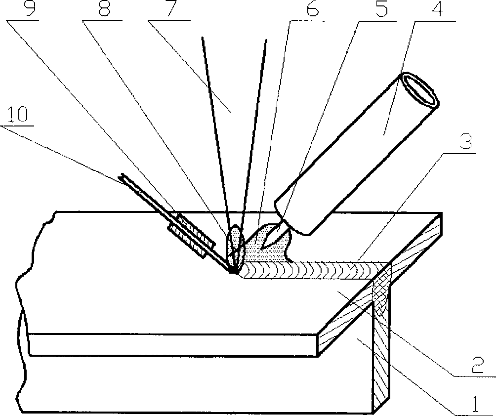
[0023] The method of this embodiment is basically the same as that of Embodiment 1, and the only difference is that this method adds a filler wire 10 when welding, see the attached image 3 . The welding wire 10 and the arc 6 are arranged on both sides of the laser beam 7, and the welding wire 10, the laser beam 7, the arc 6 and the rib 1 are arranged on a plane.


PUM


Abstract

The invention relates to a laser-arc composite welding method for a T-shaped joint of a thin plate, belonging to the technical field of laser materials processing. The method adopts a laser-arc composite thermal source to complete the welding of the T-shaped joint on the lateral face of a bottom plate, a laser bean enters from the top face of the bottom plate, an electric arc is in paraxial arrangement at the front part or the rear of the laser bean, and the composite thermal source accomplishes the penetration fusion welding from the lateral face of the bottom plate of the T-shaped joint. The welding seam of the joint welded by the method is favorably shaped, a weld toe of the connection part of a rib plate and the bottom plate is uniformly and smoothly transited, and air holes, cracks and other defects are not presented after the welding seam is anatomized. The method fully utilizes the characteristics of the composite thermal source; and under the mutual actions of laser and arc, the stability of a welding process is obviously improved, the welding efficiency is increased, and the welding deformation can be lessened.

Description

technical field [0001] The invention relates to a laser-arc composite welding method for a T-shaped joint of a thin plate, belonging to the technical field of laser material processing. Background technique [0002] In aerospace, ships, and high-speed train industries, in order to achieve lightweight structures, reduce weight, reduce energy consumption, and save material consumption, the welded structure design composed of skin and skeleton represented by T-shaped joints has become one of the mainstream technologies. One, and has been successfully applied to large-scale components. [0003] With the characteristics of reliable process, low deformation and flexibility, laser welding technology has become the most technical and economical processing method for this type of structural connection, and has successfully replaced the traditional riveting process. For example, on the empty shell A340 aircraft, the T-joint composed of the fuselage skin and the inner support beam ado...

Claims


Application Information

Patent Timeline
Patent Type & Authority Applications(China)
IPC IPC(8): B23K28/02B23K26/346
Inventor 肖荣诗吴世凯杨武雄陈铠
Owner BEIJING UNIV OF TECH
Learn More