Crosslapper

A cross-lapper and web-laying technology, which is applied to roll-forming mechanisms, textiles and papermaking, fiber processing, etc., can solve problems such as uneven surface shape of non-woven fabrics and non-straight laying of fiber webs.

Inactive Publication Date: 2015-06-10
TRUETZSCHLER GMBH & CO KG
View PDF7 Cites 25 Cited by
  • Summary
  • Abstract
  • Description
  • Claims
  • Application Information

AI Technical Summary

Problems solved by technology

In addition, due to the inclined output belt, the laying of the fiber web is not straight, thus forming inclined web edges, which re

Method used


Image

  • Crosslapper
  • Crosslapper
  • Crosslapper

Examples


Embodiment Construction

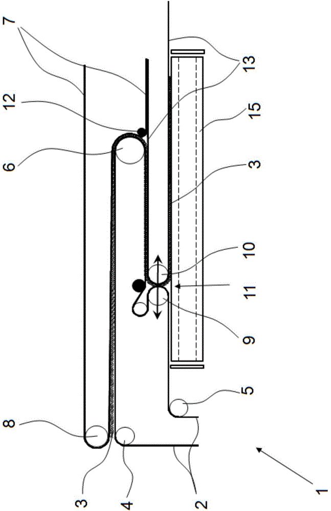
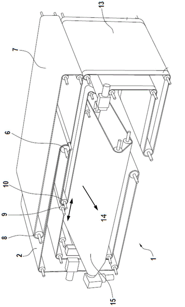
[0023] exist figure 1 and 2 The principle of the crosslapper 1 is shown by way of example and only schematically. Triggered by a card not shown, the fiber web 3 is conveyed onto the input belt 2 of the crosslapper 1 . Inside the crosslapper 1 is arranged an upper trolley, in which only the deflection rollers 6 can be seen in this view. Furthermore, the crosslapper 1 has a laying trolley, of which a laying roller 10 for the matching belt 13 and a laying roller 9 for the infeed belt 2 are shown. Between the laying roller 10 of the mating belt 13 and the laying roller 9 of the infeed belt 2 a so-called laying gap 11 is arranged, from which the fiber web 3 emerges and is laid on Output belt 15 on. Depending on the direction of travel, the two laying rollers 9 , 10 take over the task of laying the fiber web 3 perpendicular to the preceding direction of travel on a delivery belt 15 arranged below the laying carriage and simultaneously folding it. For this purpose, the laying tr...


PUM


Abstract

The invention relates to a crosslapper used for a multi-layer fibre web to form non-woven fabrics.The crosslapper comprises at least one belt used for conveying the fibre web (3) from an input area of the crosslapper (1) to a lapping gap (11) of a lapping pulley. During the process, the lapping pulley enables the fibre web to be laid on an output belt (15). The crosslapper is characterized in that the output belt (15) is provided with a mechanism used for forming a horizontal segment (15a) in an area at a laying position of the output belt (15) of the fibre web (3).

Description

technical field [0001] The present invention relates to a crosslapper for forming nonwoven fabrics from multilayer webs. Background technique [0002] Carding machines with subsequent crosslappers are usually used for the production of multilayer nonwovens. In a carding device, fiber batts are supplied on the input side, are debonded until individual fibers are formed, and are output on the output side in the form of an unconsolidated textile planar structure, ie a fiber web. [0003] The crosslapper transports the fiber web to an output belt arranged at 900 to the input direction, and lays the fiber web on the output belt in multiple layers with a predetermined laying width. The nonwoven thus formed can then be consolidated in a subsequent needling machine. The relationship between the input speed of the crosslapper and the output speed of the output belt determines the laminate to be achieved, ie the number of layers of the fiber web in the flat structure "nonwoven" to b...

Claims


Application Information

Patent Timeline
IPC IPC(8): D04H1/74
CPCD01G25/00D04H1/74D04H11/04
Inventor 莱因霍尔德·多林斯文·汤姆森
Owner TRUETZSCHLER GMBH & CO KG
Why Eureka
Try Eureka