
Lens filtering device

A filter device and lens technology, applied in the direction of installation, optics, optical components, etc., can solve the problems of increased design and manufacturing costs such as mold opening costs, easy deformation of switching devices, and many parts, etc., to achieve convenient and fast assembly. The effect of simplicity and few parts

Inactive Publication Date: 2015-06-10
UNION OPTECH
View PDF5 Cites 3 Cited by
  • Summary
  • Abstract
  • Description
  • Claims
  • Application Information

AI Technical Summary

Problems solved by technology

[0002] Now on the market, the switching device used for the lens is generally made into a drawer-shaped structure, and the thickness of the front end is extremely thin, within 2mm. Therefore, the switching device is prone to deformation or damage during transportation or assembly; the entire The switching device is fixedly connected to the base by screws. Due to the above-mentioned design structure, there are many parts, which increases the design and manufacturing costs such as the corresponding mold opening cost.

Method used


Image

  • Lens filtering device
  • Lens filtering device
  • Lens filtering device

Examples


Embodiment Construction

[0025] Embodiments of the present invention will be described in detail below in conjunction with the accompanying drawings.

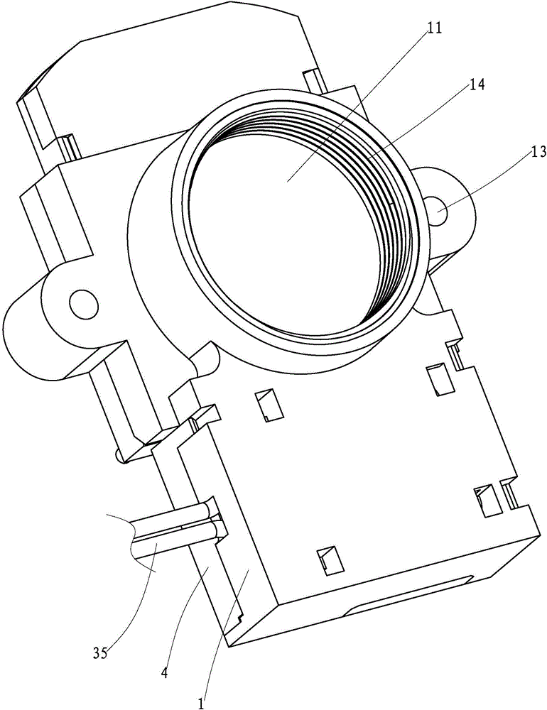
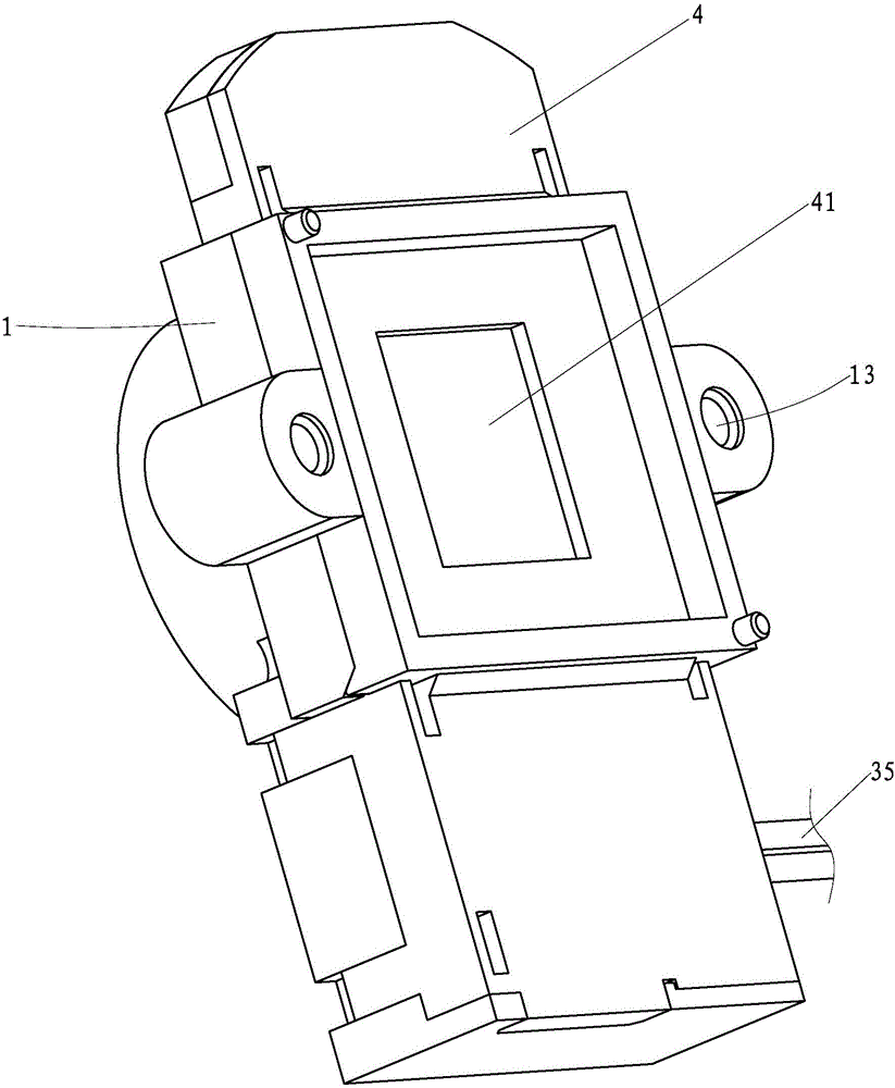
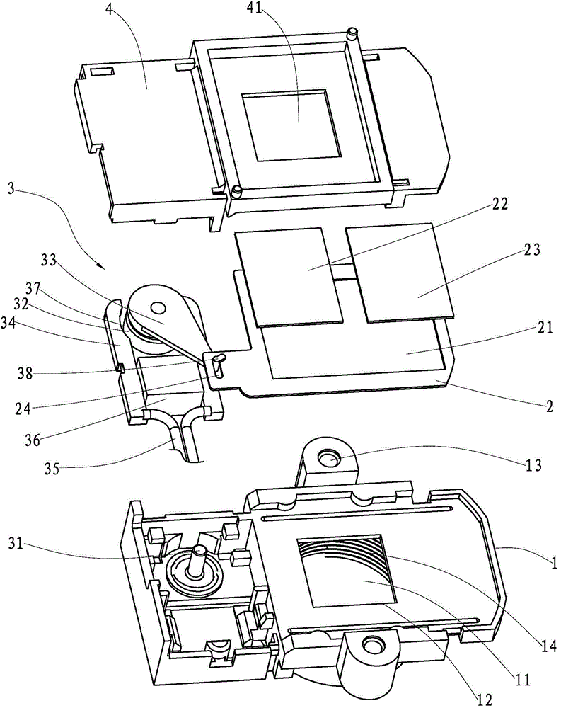
[0026] A lens filter device of the present invention comprises a base 1, a switch plate 2, a switch drive mechanism 3 and an upper cover.

[0027] The front of the base 1 is provided with a lens connection hole 11 for connecting with the lens, the lens connection hole 11 is provided with an internal thread 14, and the back of the base 1 is provided with a base light guide connected to the lens connection hole 11. Holes 12, positioning connection holes 13 for connecting with the imaging module are provided on both sides of the base 1.

[0028] The switching piece 2 is slidably connected to the back of the base 1, the switching piece 2 is provided with a switching hole 21 corresponding to the light guide hole 12 of the base, and the switching piece 2 is provided with a switching hole 21 for blocking The first filter 22 and the second filter 23;

[0029...


PUM


Abstract

The invention discloses a lens filtering device. The device comprises a base, a switching sheet, a switching driving mechanism and an upper cover; the lens is fixedly connected through a lens connecting hole in the base; a first light filter and a second light filter are arranged on the switching sheet; the switching driving mechanism acts on the switching sheet to switch the first light filter and the second light filter. The lens filtering device has the advantages that the structure is simple, few parts are used, the filtering stability of the switching sheet can be improved, and meanwhile, switching sheet can be conveniently assembled to a lens.

Description

【Technical field】 [0001] The invention relates to a lens assembly, in particular to a lens filter device. 【Background technique】 [0002] Now on the market, the switching device used for the lens is generally made into a drawer-like structure, and the thickness of the front end is extremely thin, within 2mm. Therefore, the switching device is prone to deformation or damage during transportation or assembly; the entire The switching device is fixedly connected to the base by screws. Due to the adoption of the above-mentioned design structure, there are many components, which increases the corresponding design and manufacturing costs such as mold opening costs. [0003] The present invention studies and proposes aiming at the deficiencies in the prior art. 【Content of invention】 [0004] The technical problem to be solved by the present invention is to provide a lens filter device, which includes a base, a switching piece, a switching drive mechanism and an upper cover. Th...

Claims


Application Information

Patent Timeline
Patent Type & Authority Applications(China)
IPC IPC(8): G02B7/00
CPCG02B26/008
Inventor 梁海清蔡宾吕祖文刘辉黄振锋孔祥锐邱盛平
Owner UNION OPTECH
Learn More