Lens assembly and lighting device

A lens group and lens technology, applied in lighting devices, fixed lighting devices, components of lighting devices, etc., can solve problems such as inability to achieve generalization and conversion, differences in lamp design and processing, insufficient road lighting, etc., to reduce costs and The effect of installation time, improved utilization, and improved installation efficiency

Pending Publication Date: 2021-10-26
OPPLE LIGHTING +1
View PDF0 Cites 0 Cited by
  • Summary
  • Abstract
  • Description
  • Claims
  • Application Information

AI Technical Summary

Problems solved by technology

However, in the lighting mode of center lighting, the brightness of the two sides of the above-mentioned lamps is inconsistent when working, resulting in insufficient lighting on one side of the road
[0003] During the research and practice of the prior art, the inventors of the present application found that when road lamps adopt different lighting arrangements, there are large differences in the design and processing of the lamps, and it is impossible to achieve universal and conversion

Method used


Image

  • Lens assembly and lighting device
  • Lens assembly and lighting device
  • Lens assembly and lighting device

Examples


Embodiment 1

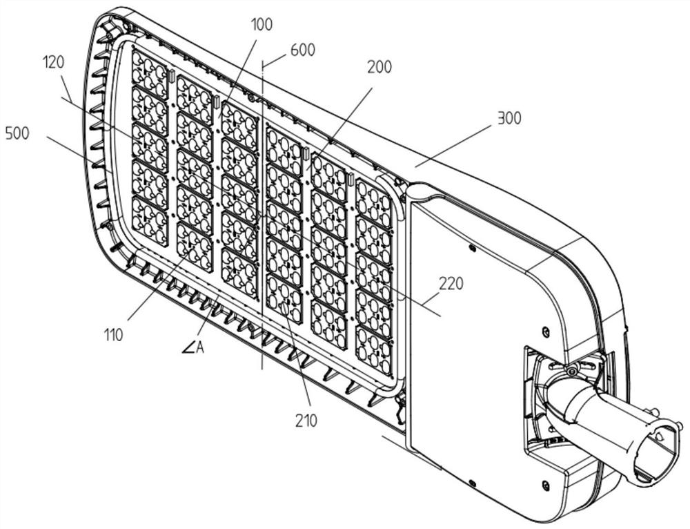
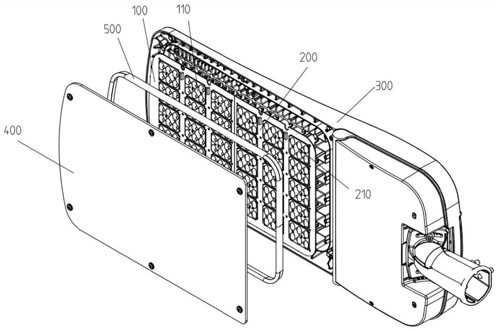
[0036] The first embodiment of the present application provides a lighting device, specifically a road lighting appliance, which can realize simultaneous light distribution on both sides by combining the lamps used in the lighting arrangement on both sides of the road. Therefore, the lighting in this application The device can be applied to road lighting such as tunnels that require central lighting. Such as Figure 1-Figure 7 As shown, the lighting device includes a housing 300, a light source (not shown in the figure) and a lens assembly, wherein the lens assembly and the light source are arranged correspondingly to deflect light from the light source in different directions. After the lighting device is installed in the way of central lighting, it can use the lens assembly to realize light distribution on both sides of the road, so as to meet the lighting requirements of the road. In this application, in order to improve the lighting effect and make the light source and th...

Embodiment 2

[0045] Compared with the first embodiment, this embodiment includes all the technical features of the first embodiment, and also includes the following features, the clamp between the central axis 120 of the first lens module 100 and the central axis 220 of the second lens module 200 The angle is 180°, that is, the angle A between the first central axis 120 and the second central axis 220 is 180°. Both the first light spot and the second light spot mainly cover the road, which can not only enhance the brightness of road lighting, but also improve the utilization rate of light. In addition, the plane where the surface of the first lens module 100 is located is coplanar with the plane where the surface of the second lens module 100 is located, and the angle A between the first central axis 120 and the second central axis 220 is 180°, which can facilitate Determining the installation positions of the first lens module 100 and the second lens module 200 reduces the difficulty of a...

Embodiment 3

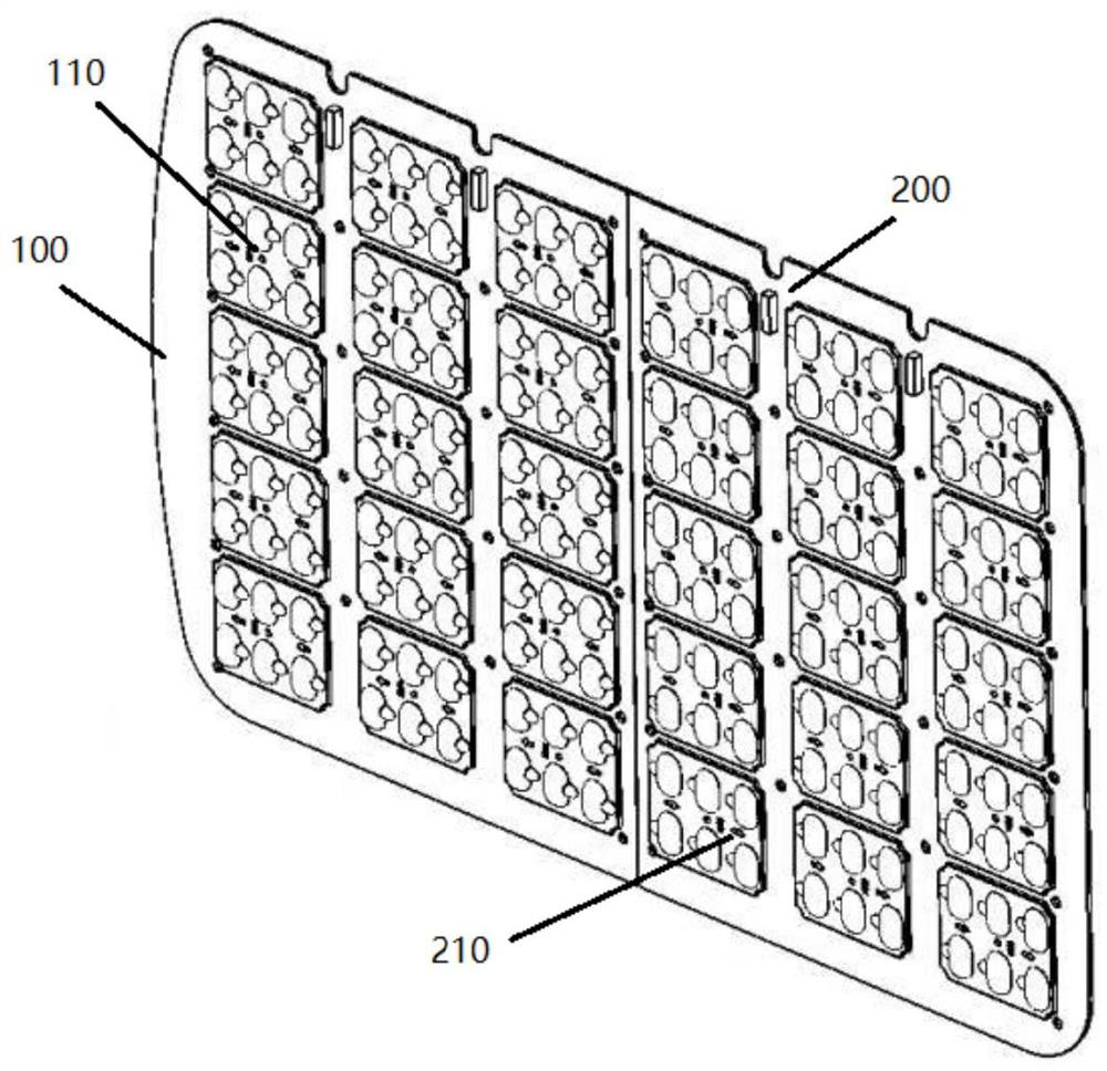
[0047] This embodiment includes all the technical characteristics of Embodiment 2, and it also includes the following technical characteristics, the first lens group 110 and the second lens group 210 are the same, so the brightness and range of the first light spot and the second light spot are consistent; The first lens module 100 and the second lens module 200 are convenient for determining the degree of the included angle according to the coverage area and brightness of the light spot, thus it is convenient for determining the relative position of the first lens module 100 and the second lens module 200 . At the same time, the first lens group 110 and the second lens group 210 each include a number of lenses, each of which has the same structure and is arranged opposite to each other along the centerline 600. In this application, the centerline is the first lens group 110 and the second lens group 210 line of symmetry between them. Since the first lens group 110 and the sec...


PUM

PropertyMeasurementUnit
Degreeaaaaaaaaaa

Abstract

The embodiment of the invention discloses a lens assembly and a lighting device. The lens assembly comprises a first lens module which comprises a plurality of first lens groups, and a second lens module which comprises a plurality of second lens groups, wherein the first lens module and the second lens module are symmetrically arranged in parallel. The lens assembly limits the relative positions of the first lens module and the second lens module through a combination which is coplanar and forms an included angle so that light spots of the first lens group and light spots of the second lens group can be projected in different directions. The application of a unilaterally mounted lamp in a central lamp distribution scene and the universality and conversion of the lamp in different lamp distribution modes are realized, and the utilization rate of the lens assembly is improved.

Description

technical field [0001] The present application relates to the field of road lighting facilities, in particular to a lens assembly and a lighting device. Background technique [0002] The lamps used for lighting in existing tunnels and other roads can adopt different lighting methods such as lighting on both sides or central lighting. When using the lighting method of lighting on both sides, in order to improve the utilization rate of light and project more spots on the road, the lamps will polarize the light in one direction. However, in the lighting mode of the center lighting, the brightness of the two sides of the above-mentioned lamps is inconsistent when it is working, resulting in insufficient lighting on one side of the road. [0003] During the research and practice of the prior art, the inventors of the present application found that when road lamps are arranged in different ways, there are large differences in the design and processing of the lamps, and it is impo...

Claims


Application Information

Patent Timeline
IPC IPC(8): F21S8/04F21V5/04F21W131/101F21Y115/10
CPCF21S8/04F21V5/04F21W2131/101F21Y2115/10
Inventor 高丰郭金明李京蔓刘超博刘动卫庆军
Owner OPPLE LIGHTING
Why Eureka
Try Eureka