Vehicle B column fracture test method and system

A fracture test and B-pillar technology, applied in the field of vehicle safety, can solve the problems of large manpower and time consumption, high cost, and difficult main reasons, and achieve the effects of ensuring accuracy, improving efficiency, and saving R&D and manufacturing costs

Active Publication Date: 2021-09-21
VOYAH AUTOMOBILE TECH CO LTD
View PDF6 Cites 0 Cited by
  • Summary
  • Abstract
  • Description
  • Claims
  • Application Information

AI Technical Summary

Problems solved by technology

However, this method still has the following disadvantages: 1. It is difficult to accurately predict the fracture of the B-pillar in the simulation of the vehicle level. In the vehicle collision simulation, there are many factors that affect the accuracy of the simulation (such as the acquisition of simulation material parameters, such as Including glass, sheet metal, rubber and other materials), it is a great challenge for the simulation to truly simulate the failure of the fracture, and the calculation results of the models provided by different companies on the simulation platform will also be different, which will cause simulation and Deviation of test results; 2. If the prediction in the simulation stage is not accurate enough, and the B-pillar breaks in the vehicle crash test, due to the large number of parts involved, it is difficult to identify the main cause of the B-pillar break, which needs to be checked one by one. It will consume a lot of manpower and time; 3. If the B-pillar breaks in the vehicle crash test, the cost of rectification will be relatively high, usually involving the reopening of the B-pillar mold, increasing the R&D and manufacturing of the vehicle

Method used


Image

  • Vehicle B column fracture test method and system
  • Vehicle B column fracture test method and system
  • Vehicle B column fracture test method and system

Examples


Embodiment Construction

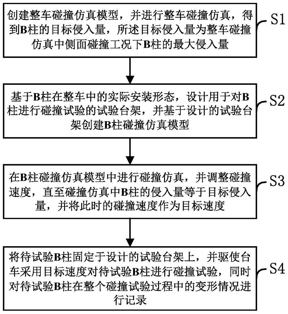
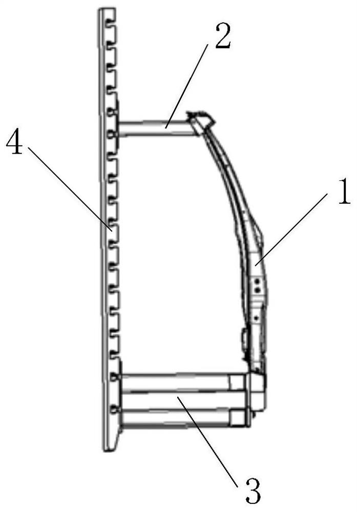
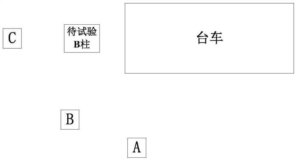
[0040] An embodiment of the present invention provides a vehicle B-pillar fracture test method. By creating a vehicle collision simulation model and performing a vehicle collision simulation, the target intrusion amount of the B-pillar is obtained, and a test bench is designed for performing a collision test on the B-pillar. , and create a B-pillar collision simulation model based on the designed test bench to carry out collision simulation in the B-pillar collision simulation model, and obtain the target speed to reach the target intrusion when a single B-pillar collides, and then fix it on the test bench based on the target speed The B-pillar to be tested on the rack is collided to simulate the real collision scene of the B-pillar, and the collision result close to the real collision scene is obtained to ensure the accuracy of the collision result. The cost of vehicle R&D and manufacturing can also effectively improve the efficiency of B-pillar fracture investigation, saving ...


PUM


Abstract

The invention discloses a vehicle B column fracture test method and system, and relates to the field of vehicle safety, and the method comprises the steps: creating a whole vehicle collision simulation model, and carrying out the whole vehicle collision simulation, and obtaining the target intrusion amount of a B column; based on the actual installation form of the B column in the whole vehicle, designing a test bed for carrying out a collision test on the B column, and creating a B column collision simulation model based on the designed test bed; performing collision simulation in the B column collision simulation model, adjusting the collision speed until the intrusion amount of the B column in the collision simulation is equal to the target intrusion amount, and the collision speed at the moment serving as the target speed; fixing a to-be-tested B column on a designed test bench, driving the trolley to perform a collision test on the to-be-tested B column at the target speed, and meanwhile, recording the deformation condition of the to-be-tested B column in the whole collision test process. According to the invention, the research and development and manufacturing cost of the vehicle can be effectively saved, the B-pillar fracture troubleshooting efficiency can be effectively improved, and time and labor are saved.

Description

technical field [0001] The invention relates to the field of vehicle safety, in particular to a vehicle B-pillar fracture test method and system. Background technique [0002] In daily life, some traffic accidents often occur, and the B-pillar of the vehicle body breaks, causing casualties. In order to reduce casualties, vehicle safety regulations are also gradually tightened. At the same time, consumers' requirements for vehicle safety performance are also constantly improving, so the requirements for safety performance in vehicle body design are also getting higher and higher. However, in vehicle design It is difficult to accurately assess whether the B-pillar will break in the event of a collision. [0003] At present, mainstream car companies will establish a collision simulation model of the entire vehicle in the vehicle development stage to predict the collision performance of the B-pillar through simulation. However, this method still has the following disadvantages...

Claims


Application Information

Patent Timeline
IPC IPC(8): G01M7/08G01M17/007
CPCG01M7/08G01M17/0078
Inventor 陆兴旺谢满罗洲刘国平唐彪
Owner VOYAH AUTOMOBILE TECH CO LTD
Why Eureka
Try Eureka