Rotary motor rotor

A technology for rotating electrical machines and rotors, applied in the field of rotors of rotating electrical machines, can solve problems such as uneven temperature, uneven cooling effect of rotor core and rotor rod, and unbalanced ventilation volume.

Active Publication Date: 2015-06-10
TOSHIBA MITSUBISHI-ELECTRIC IND SYST CORP
View PDF4 Cites 0 Cited by
  • Summary
  • Abstract
  • Description
  • Claims
  • Application Information

AI Technical Summary

Problems solved by technology

That is, the amount of ventilation in the ventilation duct is unbalanced, resulting in uneven cooling effects on the rotor core and rotor rod as cooling targets, resulting in uneven temperatures

Method used


Image

  • Rotary motor rotor
  • Rotary motor rotor
  • Rotary motor rotor

Examples


Embodiment Construction

[0011] Embodiments of the present invention will be described in detail below in conjunction with the accompanying drawings.

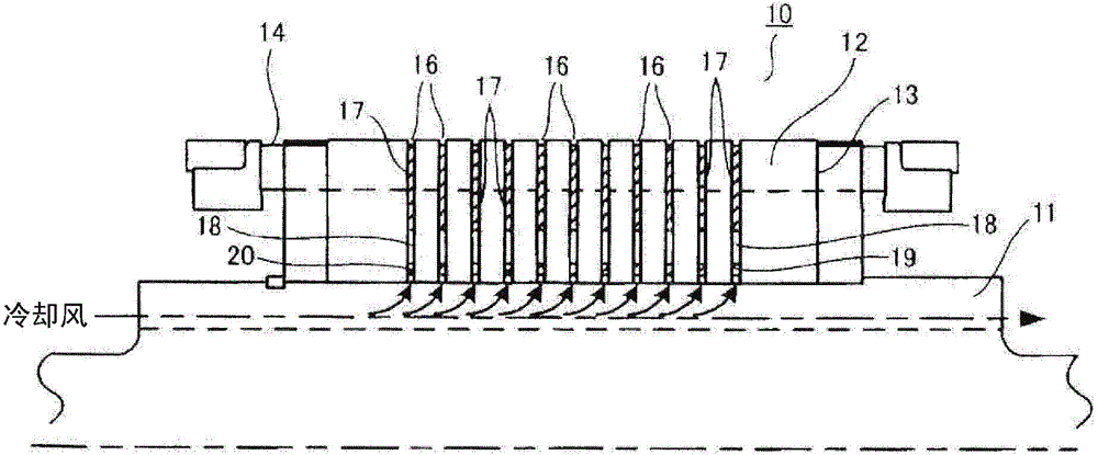
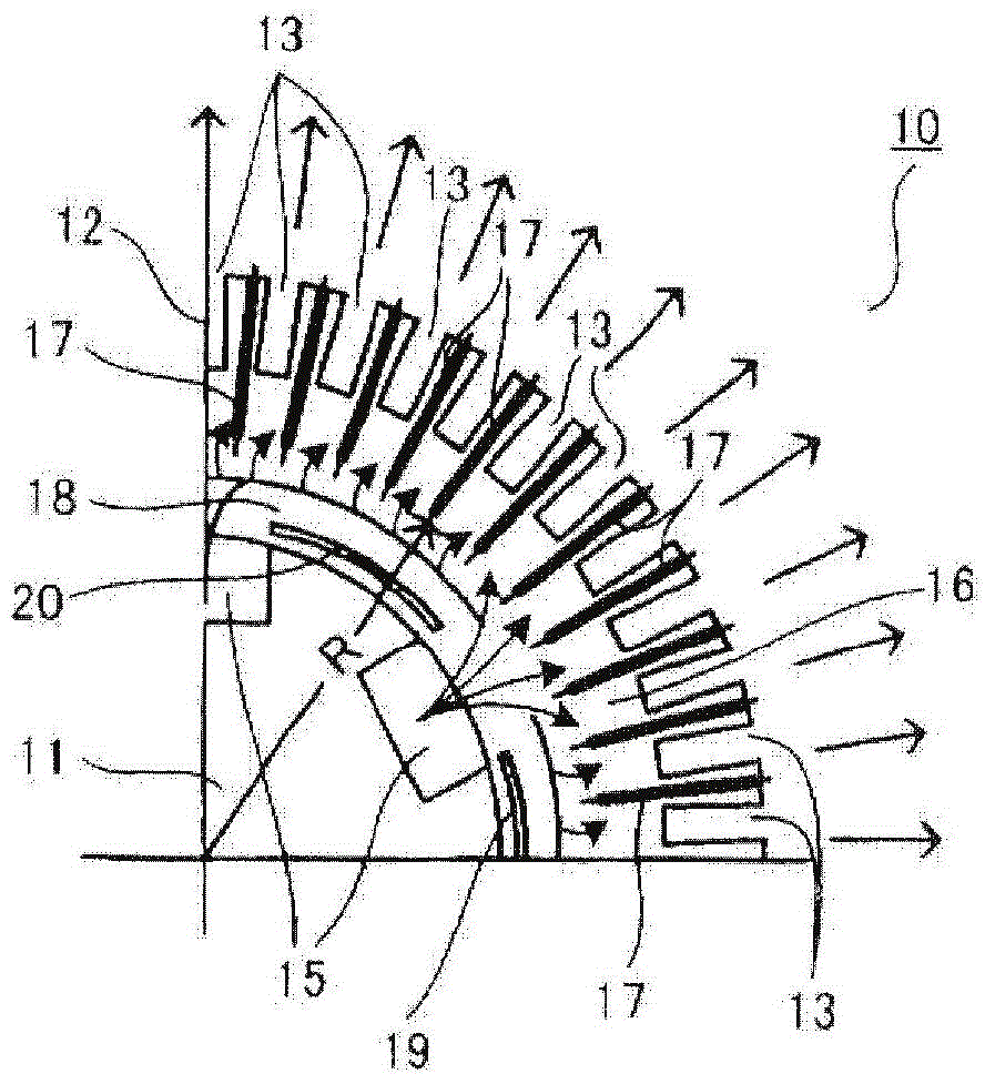
[0012] figure 1 shows the rotor 10 of the rotating electrical machine of this embodiment, figure 2 1 / 4 of the cross section of the rotor 10 is shown.

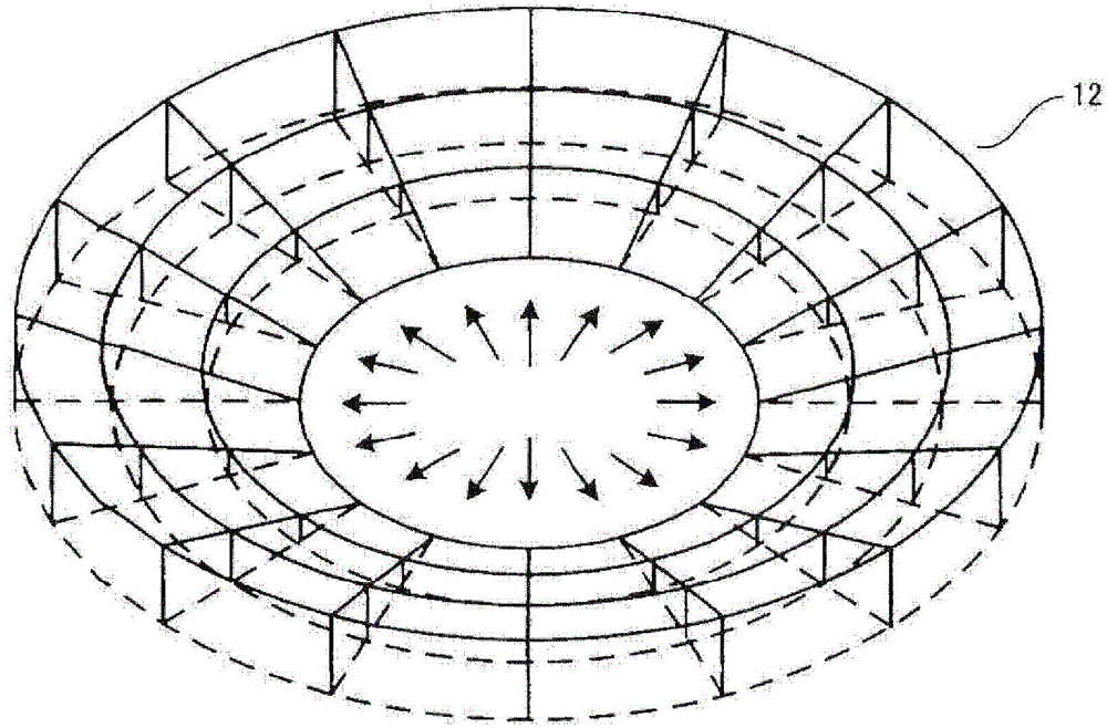
[0013] exist figure 1 and figure 2 Among them, the rotor 10 is constituted by fitting and mounting a rotor core 12 on the outer peripheral surface of a rotating shaft 11 . On the outer peripheral surface of the rotor core 12, respectively formed in the axial direction figure 2 Multiple slots 13 are shown. In addition, rotor rods 14 are respectively housed in these slots 13 .

[0014] The rotary shaft 11 has a plurality of ventilation grooves 15 formed in the axial direction on an outer peripheral surface in contact with the inner peripheral surface of the rotor core 12 . like figure 2 As shown, these ventilation slots 15 are arranged at equal intervals along the circumferential direction of ...


PUM


Abstract

A rotary motor rotor improves a ventilation cooling structure, so ventilation quantity in a ventilation pipe is uniform, thus preventing uneven cooling effect, and realizing temperature equalization of a cooled object; an outer periphery of a rotor core (12) nested with an outer periphery of a rotary shaft (11) is provided with a plurality of groovings (14) containing a rotor rod (13) in an axial direction; the outer periphery of the rotary shaft (11) is provided with a plurality of vent slots (15) arranged at intervals along the periphery in the axial direction; a plurality of portions of the rotor core (12) in the axial direction are provided with a plurality of vent pipes (16) passing an inner circle to an outer circle of the rotary core (12); a linear pipe part (17) is arranged between positions having a regulated semidiameter from the rotary center of the rotary shaft (11) and the plurality of groovings (13) in the vent pipes (16); a position, far away from the vent slot (15), between an inner side of the linear pipe part (17) and the outer periphery of the rotary shaft (11) in each vent pipe (16) is provided with an arc pipe part (20) along the periphery of the rotary shaft (11).

Description

technical field [0001] Embodiments of the present invention relate to a rotor of a rotating electric machine in which a ventilation cooling structure is improved. Background technique [0002] As described in Japanese Patent Application Laid-Open No. 62-239838, the rotor of a rotating electrical machine such as an induction motor is fitted with a rotor core and the outer peripheral surface of the rotating shaft, and a plurality of Grooving. And rotor rods (conductors) are housed in these slots, respectively. In addition, a plurality of ventilation grooves (air passages) each formed in the axial direction are arranged at equal intervals in the circumferential direction on the outer peripheral surface of the rotating shaft in contact with the inner periphery of the rotor core. Furthermore, a plurality of ventilation ducts (air ducts) leading from the inner circumference to the outer circumference of the rotor core are formed around the outer peripheral surface of the rotatin...

Claims


Application Information

Patent Timeline
Patent Type & Authority Applications(China)
IPC IPC(8): H02K1/32
CPCH02K1/32
Inventor 刘克成坪井雄一七海秀幸
Owner TOSHIBA MITSUBISHI-ELECTRIC IND SYST CORP
Why Eureka
Try Eureka