Sliding door wheel device with transverse position capable of being adjusted

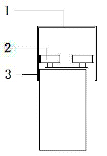
A lateral adjustment and roller technology, applied in the field of sliding doors, can solve the problems of the sliding door 3 being skewed, falling off, and the sliding door cannot continue to move, so as to achieve the effect of smooth pushing and pulling and preventing falling off.

Inactive Publication Date: 2015-06-17
KELAIFU HOUSEHOLD
View PDF7 Cites 0 Cited by
  • Summary
  • Abstract
  • Description
  • Claims
  • Application Information

AI Technical Summary

Problems solved by technology

[0002] see figure 1 , the lower part of the existing sliding door roller device 2 is fixedly connected with the sliding door 3, and the upper part is located in the upper rail 1. When the sliding door 3 is deformed, the sliding door 3 will rub against the upper rail 1, so that the sliding door cannot continue to move; In addition, the rubber sleeve on the rollers of the existing roller device 2 for sliding doors is directly placed on the rollers, which is easy to fall off from the rollers, causing the sliding door 3 to be skewed and unusable.

Method used


Image

  • Sliding door wheel device with transverse position capable of being adjusted
  • Sliding door wheel device with transverse position capable of being adjusted
  • Sliding door wheel device with transverse position capable of being adjusted

Examples


Embodiment Construction

[0014] The technical solution of this patent will be further described in detail below in conjunction with specific embodiments.

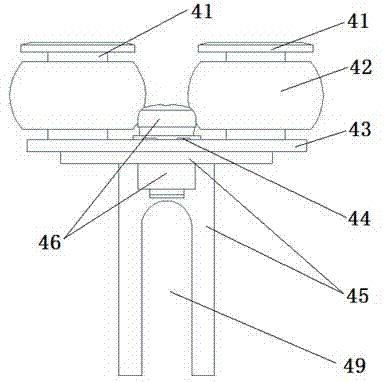
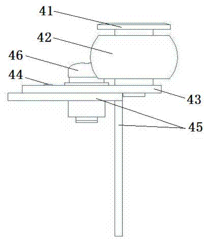
[0015] see Figure 2-5 , a roller device for sliding doors that can adjust the position horizontally, including a base 43, the two sides of the base 43 are equipped with rollers and silica gel sheaths 42 through a T-shaped roller mounting frame 41, and the top of the T-shaped roller mounting frame 41 The outer diameter of the protective cover is larger than the inner diameter of the silicone sheath of the roller and the silicone sheath 42, effectively preventing the silicone sheath from falling off from the roller; the base 43 is provided with parallel guide grooves 47 and installation grooves 48, and the guide grooves 47 and the mounting groove 48 are perpendicular to the sliding door 3; the bottom of the mounting groove 48 is equipped with an L-shaped mounting frame 45 through a bolt 46, and the vertical plate of the L-shaped mounting frame 45 is...


PUM


Abstract

The invention discloses a sliding door wheel device with the transverse position capable of being adjusted. The sliding door comprises a base. The two sides of the base are provided with wheels and silica gel protection sleeves through T-shaped wheel installation frames, and the outer diameter of upper protection covers of the T-shaped wheel installation frames is larger than the inner diameter of wheels and the inner diameter of silica gel protection sleeve bodies of the wheel and silica gel protection sleeves. A guiding groove and an installation groove which are parallel are formed in the base, and the guiding groove and the installation groove are perpendicular to a sliding door. An L-shaped installation frame is installed below the installation groove through a bolt, a vertical plate of the L-shaped installation frame is provided with an n type groove used for being installed on the sliding door, and at least two guide pillars on a flat plate of the L-shaped installation frame are inserted in the guiding groove. When the sliding door rubs an upper rail due to deformation, the transverse position of the sliding door wheel device on the sliding door can be adjusted, the sliding door can return to the original position, and smooth pushing and pulling are ensured. In addition, due to the design of the T-shaped wheel installation frames, the silica gel protection sleeves are effectively prevented from disengaging from the wheels.

Description

technical field [0001] The invention relates to the field of sliding doors, in particular to a roller device for sliding doors capable of laterally adjusting the position. Background technique [0002] see figure 1 , the lower part of the existing sliding door roller device 2 is fixedly connected to the sliding door 3, and the upper part is located in the upper rail 1. When the sliding door 3 is deformed, the sliding door 3 will rub against the upper rail 1, so that the sliding door cannot continue to move; In addition, the rubber sleeve on the roller of the existing sliding door roller device 2 is directly placed on the roller, which is easy to fall off from the roller, causing the sliding door 3 to be crooked and unusable. Contents of the invention [0003] The purpose of the present invention is to provide a horizontally adjustable roller device for sliding doors, so as to solve the problems raised in the above-mentioned background technology. [0004] To achieve the ...

Claims


Application Information

Patent Timeline
Patent Type & Authority Applications(China)
IPC IPC(8): E05D13/00
Inventor 杨红雨胡恒峰
Owner KELAIFU HOUSEHOLD
Why Eureka
Try Eureka