Planar transformer and electrical component

A technology for planar transformers and electrical components, which is applied to the parts of transformers/inductors, transformers, electrical components, etc., to avoid local corrosion, save time and cost

Active Publication Date: 2015-06-17
SIEMENS HEALTHCARE GMBH
View PDF7 Cites 0 Cited by
  • Summary
  • Abstract
  • Description
  • Claims
  • Application Information

AI Technical Summary

Problems solved by technology

Furthermore, since a gold plated surface with a partially pierced gold layer can prematurely corrode and wear on the nickel layer portion of an electrical component

Method used


Image

  • Planar transformer and electrical component
  • Planar transformer and electrical component
  • Planar transformer and electrical component

Examples


Embodiment Construction

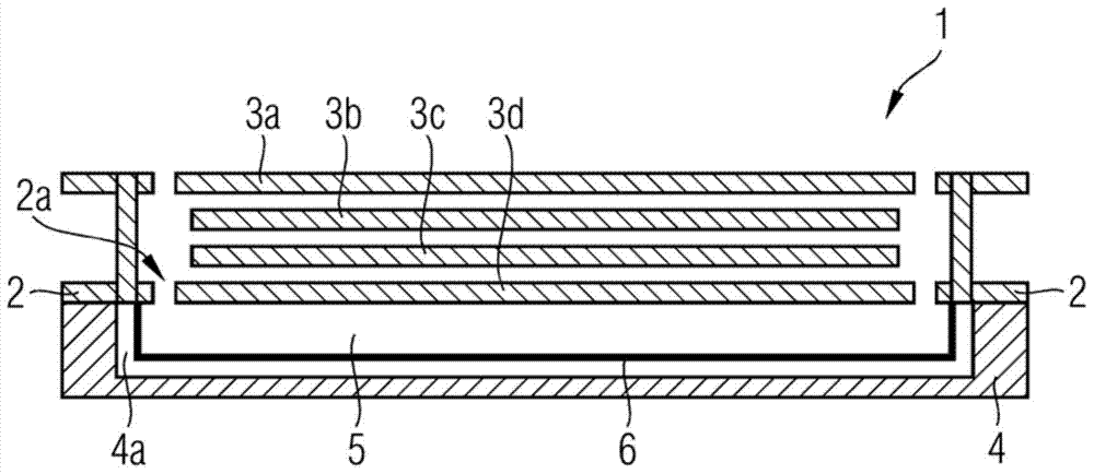
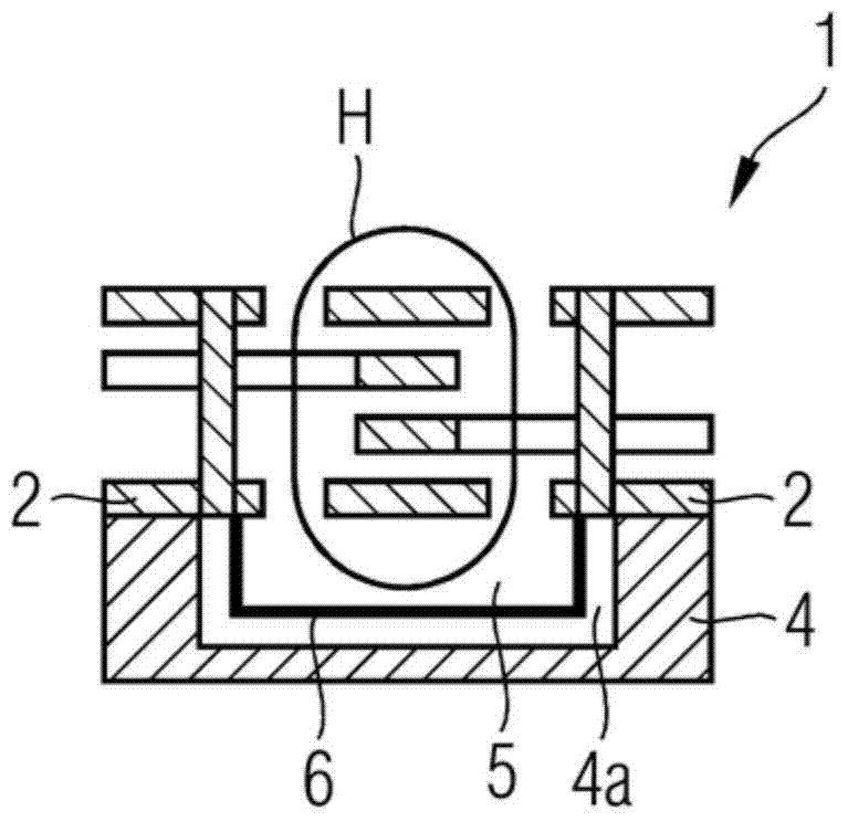
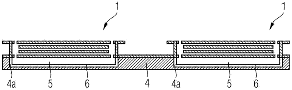
[0047] figure 1 , Figure 7 , Figure 9 , Figure 11 and Figure 13 An embodiment of the planar transformer 1 according to the invention is shown in each case in longitudinal section. for this in figure 2 , Figure 8 , Figure 10 and Figure 12 , the cross-sections of planar transformers 1 according to the present invention are shown, respectively. The basic structure of the planar transformer 1 according to the invention is described below, which is the same in each embodiment, where only the essential components of the invention and their functions are described.

[0048] The planar transformer 1 comprises a printed circuit board 2 with a rectangular milled-out opening 2a. The printed circuit board 2 is made of copper sheet with a galvanized surface and serves to support the further components of the planar transformer 1 . Furthermore, the planar transformer 1 comprises four windings arranged one above the other in the form of conductor tracks 3 a to 3 d. A magne...


PUM


Abstract

A planar transformer includes a printed circuit board, at least two conductor tracks, a base plate, and a recess that is formed in the base plate. A shroud that is formed from an at least partially electrically conductive material is arranged in the recess. The shroud is electrically connected to the printed circuit board.

Description

technical field [0001] The invention relates to a planar transformer having at least a printed circuit board, at least two conductor tracks, a base plate and a receptacle formed in the base plate. Furthermore, the invention relates to an electrical component with at least one planar transformer. Background technique [0002] Planar transformers are known from the prior art, which are implemented in the form of electrical components, in particular in the form of circuits printed on printed circuit boards. Planar transformers of this type often have return space under the printed circuit board. For this purpose, the printed circuit board has a continuous rectangular opening with a surrounding contact area. A base plate made of sheet metal can be arranged below the printed circuit board, said substrate being electrically connected to the printed circuit board in a planar manner. The base plate has a square receptacle which forms and limits a reflow space. High-frequency mag...

Claims


Application Information

Patent Timeline
Patent Type & Authority Applications(China)
IPC IPC(8): H01F27/34H01F30/06H05K1/18
CPCH01F27/2885H01F27/2804H01F27/36H01F27/363
Inventor H.克罗凯尔
Owner SIEMENS HEALTHCARE GMBH
Why Eureka
Try Eureka