Cascading static synchronous reactive compensator topology with energy exchange unit and control method thereof

A static synchronization and energy conversion technology, applied in reactive power compensation, reactive power adjustment/elimination/compensation, etc., can solve the low-pass filtering affecting the dynamic performance of cascaded static synchronous compensators, destroying control reliability, phase-to-phase Problems such as change of output current of capacitor-voltage converter

Active Publication Date: 2015-06-17
HARBIN INST OF TECH
View PDF3 Cites 12 Cited by
  • Summary
  • Abstract
  • Description
  • Claims
  • Application Information

AI Technical Summary

Problems solved by technology

[0006] The purpose of the present invention is to solve the problem that the existing star-connected cascaded converter adopts the method for unbalanced capacitor voltage between phases and phases, and the output current of the converter changes, destroying the control reliability, and t

Method used


Image

  • Cascading static synchronous reactive compensator topology with energy exchange unit and control method thereof
  • Cascading static synchronous reactive compensator topology with energy exchange unit and control method thereof
  • Cascading static synchronous reactive compensator topology with energy exchange unit and control method thereof

Examples


specific Embodiment approach 1

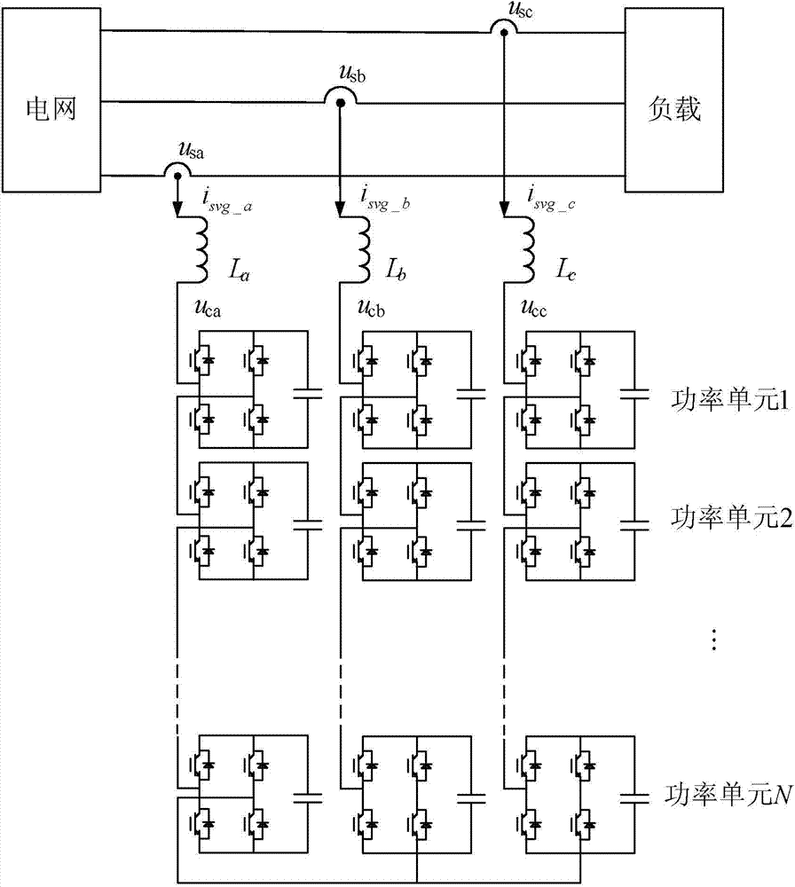
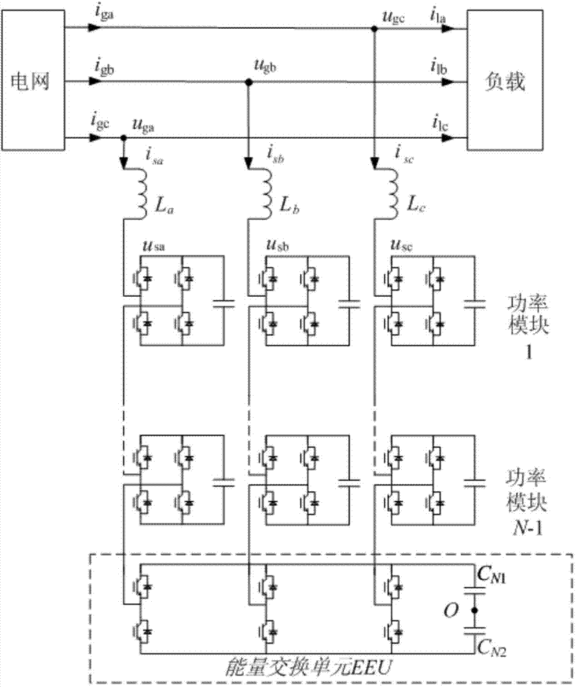
[0024] Specific implementation mode one: the following combination figure 2 Describe this embodiment, the cascaded static synchronous var compensator topology with energy conversion units described in this embodiment, the cascaded static synchronous var compensator topology includes N-1 power modules, N is a positive integer, N- 1 power module adopts star connection; the Nth power module of this cascaded static synchronous var compensator topology adopts an energy exchange unit EEU, and the energy exchange unit EEU is connected to a star point, and the energy exchange unit EEU includes a three-phase bridge and two shared capacitors C N1 、C N2 , three-phase bridge and two shared capacitors C N1 、C N2 With a star connection, the star connection point O of the energy exchange unit EEU is a zero potential point.

specific Embodiment approach 2

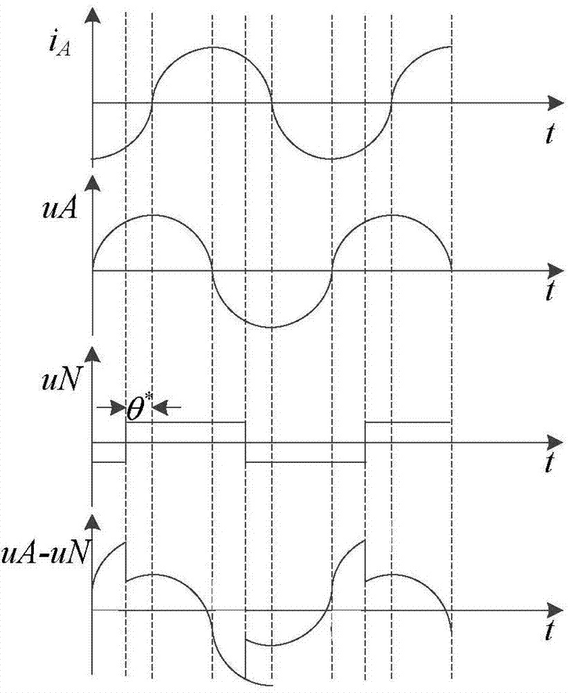
[0025] Specific implementation mode two: the following combination Figure 4 Describe this embodiment, the control method of the cascaded static synchronous var compensator topology with energy conversion units described in this embodiment, the specific process of the control method is:

[0026] Step 1. Detect the DC side voltage U of the energy exchange unit EEU DCN , put U DCN and DC side reference voltage U DCref * Subtraction, the difference is adjusted by PI to obtain the output voltage adjustment angle θ of the energy exchange unit EEU 0 ;

[0027] Step 2. Detect the three-phase capacitor voltages of A, B, and C, and obtain the average value of the three-phase capacitor voltage U avgx , put U avgx Subtract it from the reference value of the three-phase capacitor voltage, and the difference is adjusted by PI to obtain the adjustment angle θ of the output voltage of each phase x ;

[0028] Step 3. Detect the three-phase current i a i b i c , get i after 3 / 2 tran...

specific Embodiment approach 3

[0032] Specific implementation mode three: this implementation mode further explains specific implementation mode two, and adjusts the output voltage adjustment angle θ of the energy exchange unit EEU as described in step 1 0 The capacitor voltage of the energy exchange unit EEU can be kept stable.


PUM


Abstract

The invention discloses a cascading static synchronous reactive compensator topology with an energy exchange unit and a control method thereof, and relates to the power unit capacitor voltage balance control technology of a cascaded reactive compensation device. The cascading static synchronous reactive compensator topology with the energy exchange unit and the control method thereof aim at solving the problems existing in the method adopted by an existing star connection cascade converter for the capacitor voltage unbalance among phases that the output current of the converter changes and breaks the control reliability and extracting of positive and negative sequence components has lowpass filtering and influences the dynamic performance of the cascading static synchronous compensator. The cascading static synchronous reactive compensator topology comprises N-1 power modules which adopt the star connection, and the N is a positive integer; the N power module adopts the energy exchange unit EEU, the energy exchange unit EEU is connected with a star point, the energy exchange unit EEU comprises a three-phase bridge and two common capacitors, and the three-phase bridge and the common capacitors adopt the star connection. The cascading static synchronous reactive compensator topology with the energy exchange unit and the control method thereof are used in the cascaded reactive compensation device based on the power unit.

Description

technical field [0001] The invention relates to a power unit capacitor voltage balance control technology of a cascaded reactive power compensation device. Background technique [0002] The reactive power compensation device based on power unit cascading can reduce the size and power consumption of the device because it does not need a step-up transformer, and it occupies an increasingly important position in the management of medium-voltage (commonly 6kV, 10kV) power quality. In practical applications, cascaded reactive power compensation devices often choose star connection, such as figure 1 shown. Compared with the delta connection, the number of sub-modules required by the device under the same rated voltage is less, and the harmonics of the output current of the converter are smaller. [0003] The main problem of the star-connected cascaded converter is that the capacitor voltage balance between the three phases is difficult to solve. When each power module of the ca...

Claims


Application Information

Patent Timeline
IPC IPC(8): H02J3/18
CPCY02E40/30
Inventor 杨荣峰张颖琳李彬彬徐殿国王高林刘怀远
Owner HARBIN INST OF TECH
Why Eureka
Try Eureka