Method and device for achieving interface caching dynamic allocation
A dynamic allocation and dynamic configuration technology, applied in memory architecture access/allocation, memory systems, digital transmission systems, etc., can solve problems such as turbulence, system stability damage, and system traffic bursts, achieve smooth transition, and achieve dynamic sharing Effect
- Summary
- Abstract
- Description
- Claims
- Application Information
AI Technical Summary
Problems solved by technology
Method used
Image

Examples
Embodiment 1
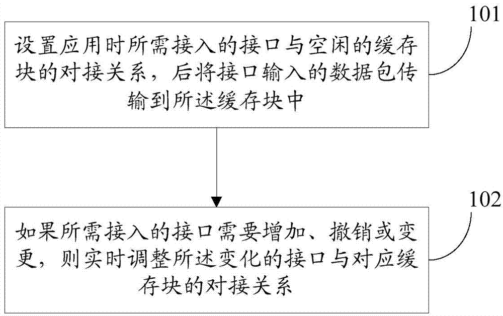
[0046]figure 1 It is a schematic diagram of the implementation flow of the method for realizing the dynamic allocation of interface cache described in the embodiment of the present invention, as shown in figure 1 As shown, the method includes:
[0047] Step 101: set the docking relationship between the interface to be accessed during the application and the free cache block in advance or when the system is running, and then transmit the data packet input by the interface to the cache block;
[0048] Here, it is assumed that the total number of interfaces supported by the system is M, and there are N cache blocks for receiving data (M≥N), but in actual use, the number of interfaces used at the same time will often not exceed N, so that N can be used The cache supports M interfaces. Wherein, the N cache blocks may be obtained by equally dividing the entire interface cache.
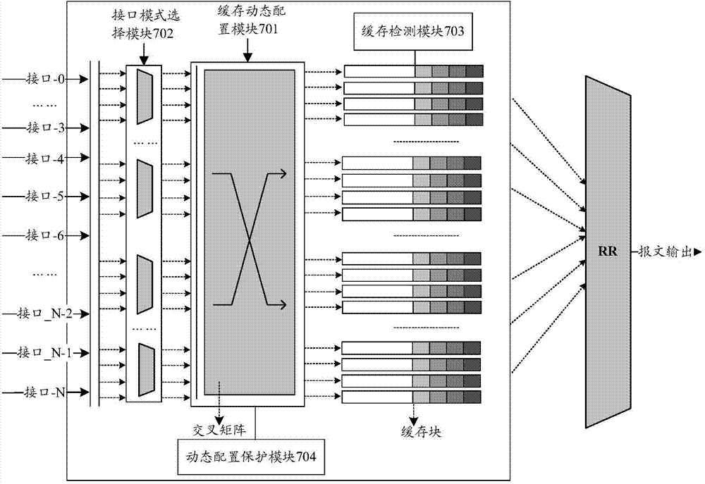
[0049] In the embodiment of the present invention, a multi-input multi-output cross matrix (input quant...
Embodiment 2
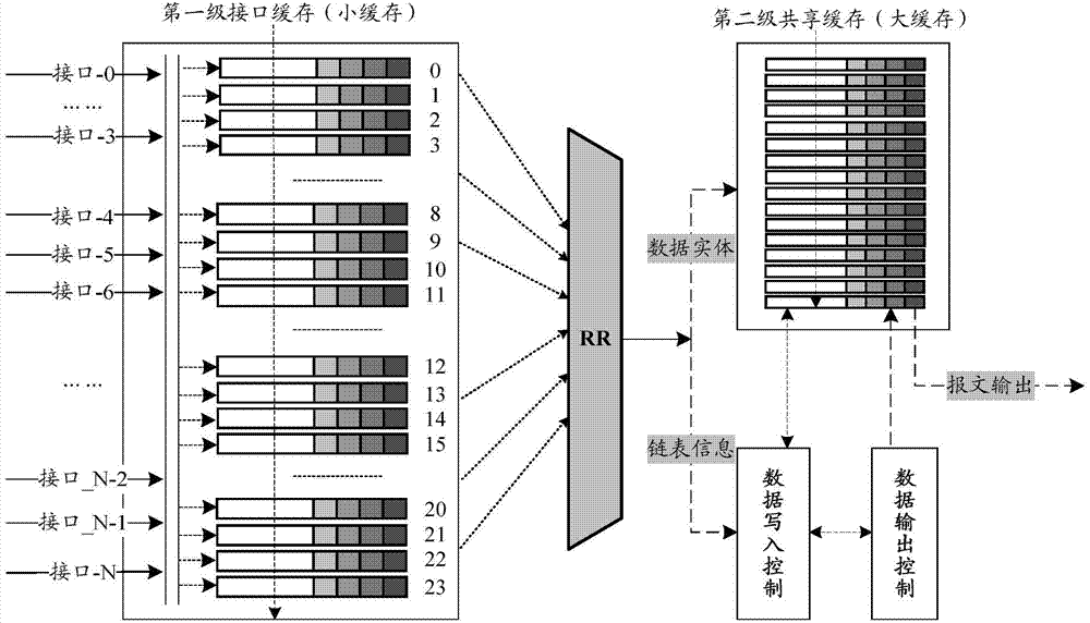
[0065] In order to clearly express the present invention and discuss the differences between the present embodiment and the cache sharing structure in the form of a linked list, the description is now based on a scenario in which multiple interfaces simultaneously receive messages. Such as figure 2 As shown, it is a cache sharing structure in the form of a linked list. Using the linked list method to deal with the simultaneous input of multiple interfaces requires a two-level cache structure. The first-level interface cache is small and is mainly used for multi-interface aggregation. The second-level shared cache has a large capacity and is used as the actual storage body of data. At the same time, each interface may send packet slices to the first-level interface cache, and each receiving cache checks the integrity of the packet, for example: checking whether the packet is a complete packet and / or a type of packet that is allowed to enter and / or Or ultra-long and ultra-shor...
Embodiment 3
[0074] The embodiment of the present invention provides an implementation method of the present invention in an application scenario, such as Figure 5 shown, including the following steps:
[0075] Step 501: According to the needs of the application scenario, determine the interface that needs to be connected, perform docking settings from the cache block to the interface, and select an idle cache block to connect to the interface;
[0076] Step 502: Configure the working mode of each interface, such as: support full packet mode / interleaved mode, and the ID number of the specific data packet received by the relevant buffer block in the interleaved mode;
[0077] Step 503: According to the setting situation, the corresponding cache block stores the message for calling by subsequent modules;
[0078] Step 504: Schedule and output the data in all cache blocks according to certain scheduling rules, such as RR, SP, etc., and send the output messages to the next level for processing...
PUM
 Abstract
Description
Claims
Application Information
 - R&D
- Intellectual Property
- Life Sciences
- Materials
- Tech Scout
- Unparalleled Data Quality
- Higher Quality Content
- 60% Fewer Hallucinations
Browse by: Latest US Patents, China's latest patents, Technical Efficacy Thesaurus, Application Domain, Technology Topic, Popular Technical Reports.
© 2025 PatSnap. All rights reserved.Legal|Privacy policy|Modern Slavery Act Transparency Statement|Sitemap|About US| Contact US: help@patsnap.com