
Oil seal

A technology for oil seals and sealing parts, which is used in bearing components, engine components, engine seals, etc.

Active Publication Date: 2015-06-17
NOK CORP
View PDF10 Cites 11 Cited by
  • Summary
  • Abstract
  • Description
  • Claims
  • Application Information

AI Technical Summary

Problems solved by technology

Therefore, it is necessary to perform an inspection based on setting the leakage allowable value, and a simple inspection cannot be performed by setting the leakage threshold value to zero (a disadvantage due to air release from the fabric)

Method used


Image

  • Oil seal
  • Oil seal
  • Oil seal

Examples


Embodiment Construction

[0071] Next, embodiments of the present invention will be described based on the drawings.

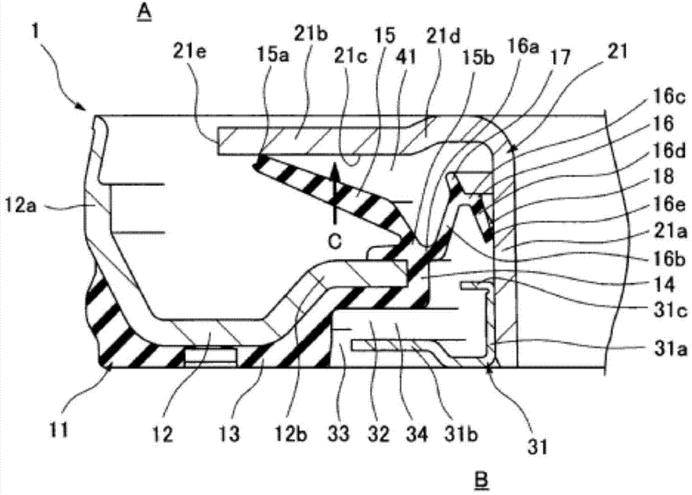
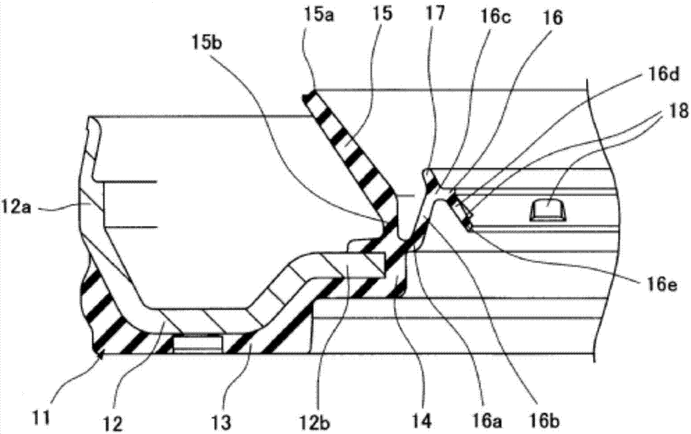
[0072] figure 1 A main part cross section of the oil seal 1 according to the embodiment of the present invention is shown, figure 2 The state before combining the lip seal member 11 and the flinger 21 in the same oil seal 1 is shown.

[0073] figure 1 The oil seal 1 shown in is composed of a lip seal member 11 fixed to the inner periphery of a shaft hole of a housing (not shown), and an oil flinger 21 fixed to a rotating shaft (not shown) inserted through the shaft hole. Combination of these components prevents leakage of sealing fluid from inside A to outside B, and at the same time prevents dust from outside B from entering inside A. In addition, a dust cover 31 is combined with the lip seal member 11 and the flinger 21 .

[0074] The flinger 21 is made of a metal material, and a flange portion 21b is integrally formed radially outward at the inner end portion of the cylindric...


PUM


Abstract

In order to provide an oil seal that is capable of reducing sliding torque to a greater extent than when fabric is used as a dust lip, a dust cover is provided together with a lip seal member and a slinger. The slinger is provided with a thread groove that provides a pumping action in a radially outward direction to an end face of a flange outside a machine. The dust cover exerts a dust shake-off action due to a centrifugal force during shaft rotation, and a labyrinth seal action due to the formation of a minute gap between the dust cover and the lip seal member. The lip seal member is provided with a main lip and dust lip. The dust lip is provided with: a first bellows part that comprises a rubber-like elastic body, is subjected to atmospheric pressure at the inner peripheral surface and is subjected to internal pressure between the lips at the outer peripheral surface; a second bellows part that is subjected to atmospheric pressure at the outer peripheral surface and is subjected to internal pressure between the lips at the inner peripheral surface; and a lip end. The pressure-receiving area of the first bellows part is established so as to be larger than that of the second bellows part.

Description

technical field [0001] The present invention relates to an oil seal as one type of sealing device related to sealing technology. The oil seal of the present invention is used, for example, in the field related to automobiles (engines), or in the field of general machinery. Background technique [0002] Such as Figure 5 As shown, an oil seal using a fabric 51 as a dust lip has been known, for example, in the field of automobile engines (diesel engines) for sealing the periphery of a crankshaft. [0003] In this prior art, the fabric 51 is constructed such that its initial inner diameter (the inner diameter before the flinger 52 is inserted) d 1 Set to the outer diameter d of the fabric sliding part of the flinger 52 2 Therefore, the fabric 51 has an interference. When the oil flinger 52 is inserted, the fabric 51 spreads along the oil flinger 52 to ensure the contact width with the oil flinger 52 . [0004] Therefore, here, since the interference amount of the fabric 51 i...

Claims


Application Information

Patent Timeline
Patent Type & Authority Applications(China)
IPC IPC(8): F16J15/32F16J15/447F16J15/3224F16J15/3244
CPCF16J15/164F16J15/32F16J15/3256F16J15/447F16J15/3244F16J15/3456F16C33/7823F16J15/002F16J15/3232
Inventor 中川岳洋
Owner NOK CORP
Learn More