Shaft-sealing device
A shaft seal and axial technology, which is applied in the direction of gas turbine devices, engine seals, engine components, etc., can solve the problems of leakage of sealing fluid to the atmosphere side, air mixing, and reduction of the pressing force of the sealing lip 60, so as to ensure the sealing performance, prevent leakage, improve pumping effect
- Summary
- Abstract
- Description
- Claims
- Application Information
AI Technical Summary
Problems solved by technology
Method used
Image
Examples
Embodiment approach 1
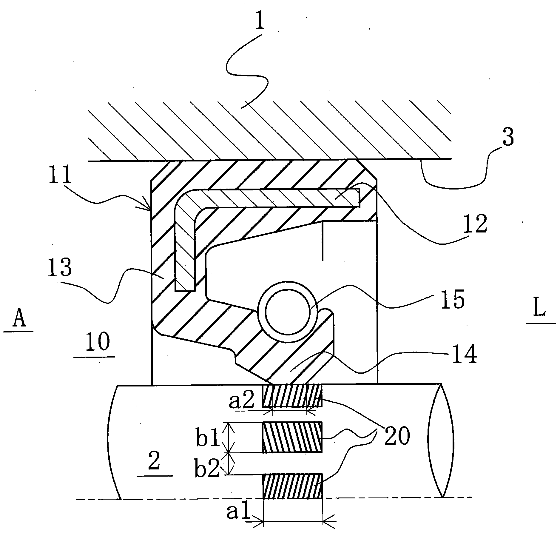
[0065] figure 1 It is a longitudinal cross-sectional view showing the shaft sealing device according to Embodiment 1 of the present invention.
[0066] in figure 1 The housing 1 is provided with a rotating shaft through hole 3 through which the rotating shaft 2 is inserted. The rotating shaft 2 is inserted through the rotating shaft through hole 3, and the rotating shaft 2 and the rotating shaft through hole are passed through a bearing etc. not shown. The rotating shaft 2 is supported with a predetermined gap between the 3 peripheral walls.
[0067] Here, with regard to the rotating member and the fixed member arranged concentrically in the radial direction inside and outside, the housing 1 corresponds to the fixed member, and the rotating shaft 2 corresponds to the rotating member.
[0068] A shaft sealing device 10 is arranged between the rotating shaft 2 and the peripheral wall of the rotating shaft through hole 3 to seal between the sealed fluid side L and the atmosphere side ...
Embodiment approach 2
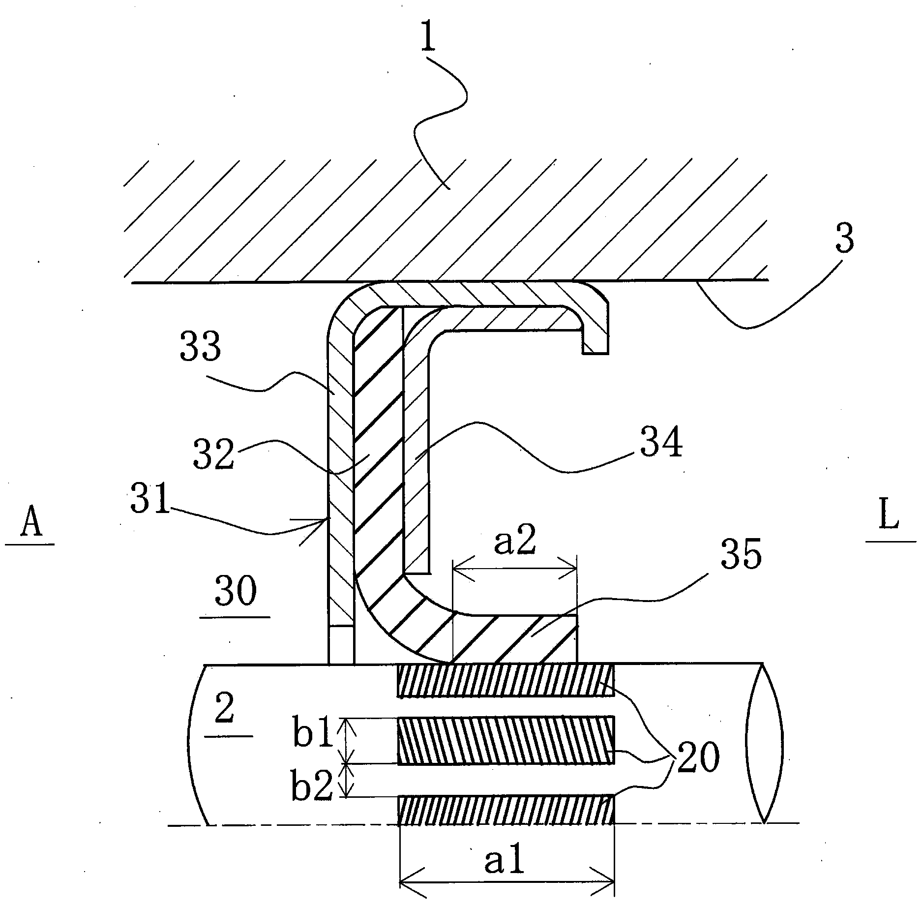
[0077] figure 2 It is a longitudinal cross-sectional view showing a shaft sealing device according to Embodiment 2 of the present invention.
[0078] in figure 2 In, and figure 1 The same label refers to the figure 1 The parts in the parts are the same, and detailed description is omitted.
[0079] The shaft sealing device 30 includes a lip seal body 31 to partition the annular space facing the housing 1 and the rotating shaft 2 into two spaces, the fluid side L and the atmospheric pressure side A, and the inside and outside of the two spaces are blocked. The lip seal body 31 includes a resin sealing lip member 32 having an L-shaped cross section. The sealing lip member 32 is composed of an outer joining metal ring 33 having a substantially L-shaped cross section and an inner pressing metal having a substantially L-shaped cross section. The ring 34 clamps.
[0080] A cylindrical lip portion 35 is formed on the inner peripheral side of the sealing lip member 32 having an L-shaped...
Embodiment approach 3
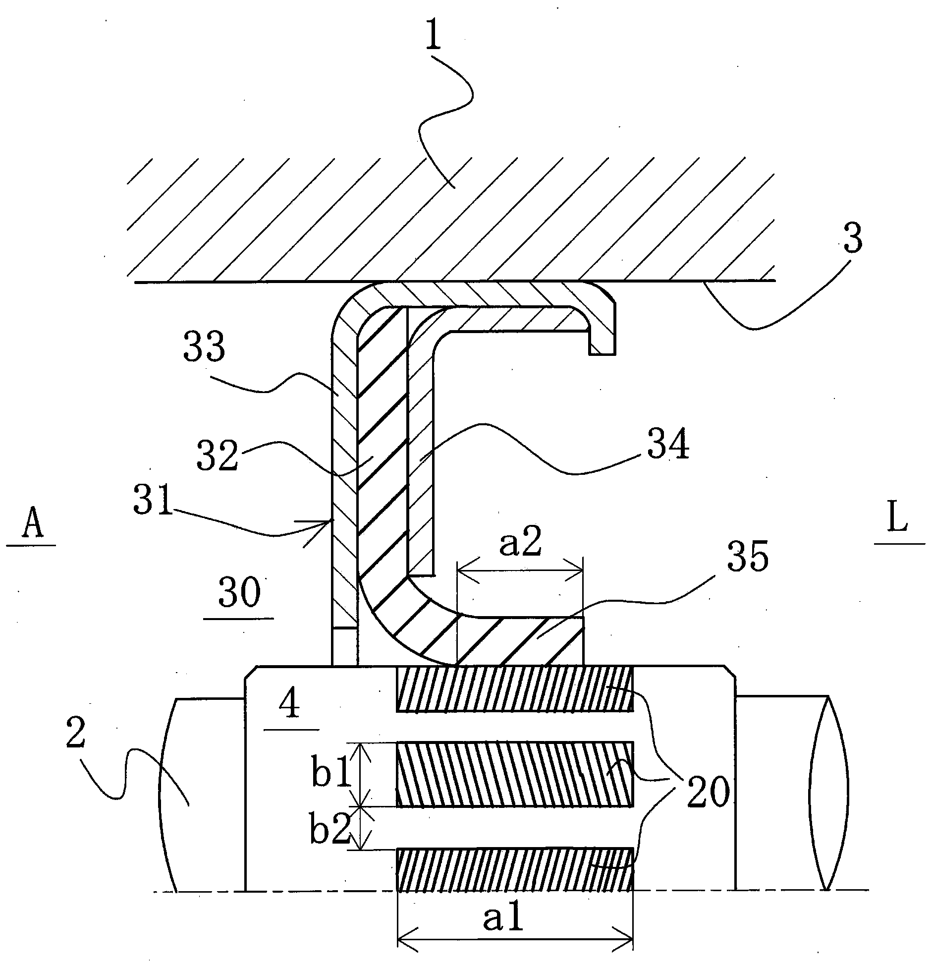
[0087] image 3 It is a longitudinal cross-sectional view showing a shaft sealing device according to Embodiment 3 of the present invention.
[0088] in image 3 In, and figure 2 The same label refers to the figure 1 The parts in the parts are the same, and detailed description is omitted.
[0089] The third embodiment differs from the second embodiment in that a sealing sleeve 4 is fitted into the rotating shaft 2. The other structure is the same as that of the second embodiment. The outer peripheral surface S of the sleeve 4 is formed in the circumferential direction. Multiple pump parts 20 separated. Here, the sleeve 4 corresponds to a rotating member.
[0090] In addition, the pump unit 20 will be described in detail below.
PUM
 Abstract
Description
Claims
Application Information
 - R&D
- Intellectual Property
- Life Sciences
- Materials
- Tech Scout
- Unparalleled Data Quality
- Higher Quality Content
- 60% Fewer Hallucinations
Browse by: Latest US Patents, China's latest patents, Technical Efficacy Thesaurus, Application Domain, Technology Topic, Popular Technical Reports.
© 2025 PatSnap. All rights reserved.Legal|Privacy policy|Modern Slavery Act Transparency Statement|Sitemap|About US| Contact US: help@patsnap.com


