Connection structure between shoe insole and shoe outsole

A technology for connecting structure and shoe outsole, which is applied to shoe soles, footwear, insoles, etc., can solve the problems of insole and shoe outsole cannot be selected, the sole cannot be disassembled and assembled at will, and the choice of consumers is limited, etc. The effect of expansion selectivity, simple structure and low implementation cost

Active Publication Date: 2017-04-12
苏州盛泽科技创业园发展有限公司
View PDF9 Cites 0 Cited by
  • Summary
  • Abstract
  • Description
  • Claims
  • Application Information

AI Technical Summary

Problems solved by technology

[0002] Shoes are composed of soles, uppers and other components. The soles generally include insoles and outsoles. In the current market, the shoes purchased by consumers are generally finished shoes. The soles of finished shoes cannot be disassembled and assembled at will. Consumers will have different requirements for the material, comfort and wear resistance of the sole, which limits the choice of consumers. Consumers can only buy finished shoes with soles selected by the manufacturer, and cannot meet their own needs. Choose insoles and outsoles
[0003] In addition, in the traditional technology, the insole and the outsole are directly connected by glue. Once the insole and the outsole are bonded, they cannot be disassembled and replaced, which is not conducive to consumers changing the outsole according to different needs. or insole

Method used


Image

  • Connection structure between shoe insole and shoe outsole
  • Connection structure between shoe insole and shoe outsole
  • Connection structure between shoe insole and shoe outsole

Examples


Embodiment 1

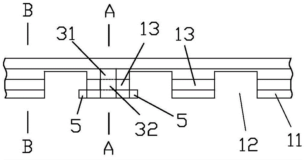
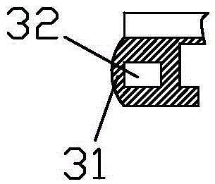
[0038] The accommodating groove 3 is formed with a rib 31 along the groove edge of the arch of the foot, and the rib 31 cooperates with the accommodating groove to form a rib hole 32, and the rib hole 32 can accommodate the shoe edge buckle 4 to pass through. Then constitute the limiting structure, see for details figure 1 , figure 2 shown.

[0039] When assembling, the shoe edge buckle 4 needs to pass through the rib hole 32. For the convenience of assembly, preferably, the shoe edge buckle 4 is formed by connecting a plurality of short shoe edge buckles 41, adjacent short The interface position of the shoe side buckle 41 is provided with cooperating locking teeth 42, and the locking teeth 42 can be pulled into the rib hole 32, and the rib hole 32 restricts the mutual matching locking teeth 42 from separating from each other. When connected on the shoe edge buckle 4, this structure is particularly suitable for sandals. Easy and fast installation, see Figure 8 .

Embodiment 2

[0041] The limiting structure includes a screw hole (not shown) arranged on the sole and a bolt (not shown) matching the screw hole. When some soles such as high-heeled shoes are relatively thick, bolt connection can be used as The limit structure, the use of bolts will not affect the wearing comfort, and the bolts themselves can also be used as decorative embellishments for high-heeled shoes, the connection is also reliable, and the assembly is quick.

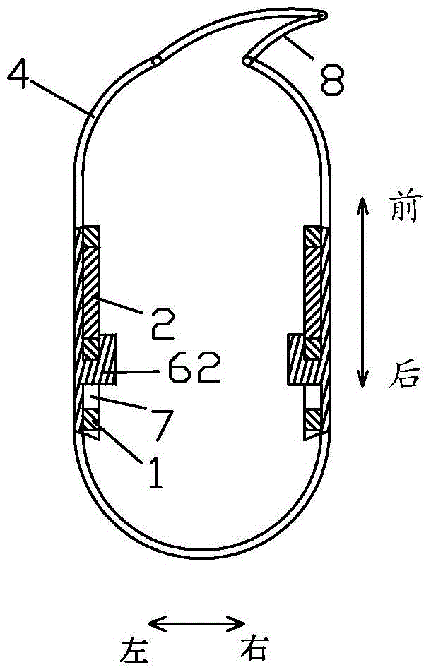
[0042] The limit structure is varied, not only can be the rib hole as described in embodiment 1, and the bolt structure described in embodiment 2, but also can be provided with tongue on the shoe side buckle, arch of foot The sole of the part is provided with a button hole 7, and the tongue 6 cooperates with the button hole 7 to make the shoe edge buckle 4 close to the outer peripheral edge of the sole to form the position-limiting structure.

[0043] more specific,

Embodiment 3

[0045] The tongue 6 is an oblique tongue 61 arranged obliquely relative to the shoe edge buckle 4 , and the buttonhole 7 is an oblique buttonhole matching the oblique tongue 61 . Specific reference Figure 10As shown, the slanted tongue 61 is like a hook. When the slanted tongue 61 is inserted into the corresponding slanted button hole, it will cooperate to form a state of hooking each other, so that the plane between the insole 1 and the outsole 2 The front, back, left, and right directions of the machine can be positioned.


PUM


Abstract

The invention discloses an insole and sole connecting structure. The insole and sole connecting structure comprises a sole body which is composed of an insole and a sole, wherein the insole and the sole are arranged independently. First raised parts and first recessed parts which are arranged alternately are included on the outer periphery of the insole in the perimeter direction. Second raised parts and second recessed parts which are arranged alternately are included on the outer periphery of the sole in the perimeter direction. The first raised parts and the first recessed parts correspond to the second raised parts and the second recessed parts in position and are embedded with the second raised parts and the second recessed parts. First grooves and second grooves are formed in the first raised parts and the second raised parts respectively, and the first grooves and the second grooves are connected end to end to form containing grooves surrounded in the outer periphery of the sole. The insole and sole connecting structure further comprises shoe edge buckle belts, and the shoe edge buckle belts are arranged in the containing grooves and are attached to the outer periphery of the sole in a surrounding mode. A limiting structure enabling the shoe edge buckle belts to be tightly attached to the outer periphery of the sole is arranged at the foot arch position of the sole. Customers can select the insole and the sole by themselves according to needs and then assemble the insole and the sole, and assembling is convenient.

Description

technical field [0001] The invention relates to a connection structure between a shoe inner sole and a shoe outsole. Background technique [0002] Shoes are composed of soles, uppers and other components. The soles generally include insoles and outsoles. In the existing market, the shoes purchased by consumers are generally finished shoes. The soles of finished shoes cannot be disassembled and assembled at will. Consumers will have different requirements on the material, comfort and wear resistance of the sole, which limits the choice of consumers. Consumers can only buy finished shoes with soles selected by the manufacturer, and cannot meet their own needs. Choose between insoles and outsoles. [0003] In addition, in the traditional technology, the insole and the outsole are directly connected by glue. Once the insole and the outsole are bonded, they cannot be disassembled and replaced, which is not conducive to consumers changing the outsole according to different needs....

Claims


Application Information

Patent Timeline
Patent Type & Authority Patents(China)
IPC IPC(8): A43B13/28A43B17/18
Inventor 温卫国
Owner 苏州盛泽科技创业园发展有限公司
Why Eureka
Try Eureka