
Crankshaft Structure for Reducing Oil Circulation Rate of Rolling Rotor Compressor

A rolling rotor type, compressor oil technology, applied to crankshafts, rotary piston type/oscillating piston type pump components, machines/engines, etc., can solve system matching performance degradation, reduce system heat exchange capacity, refrigeration/heating The capacity does not increase accordingly, to achieve the effect of improving the system matching capacity, reducing the oil circulation rate, and ensuring the cooling/heating capacity

Active Publication Date: 2018-03-06
SHANGHAI HITACHI ELECTRICAL APPLIANCES CO LTD
View PDF6 Cites 0 Cited by
  • Summary
  • Abstract
  • Description
  • Claims
  • Application Information

AI Technical Summary

Problems solved by technology

[0002] When the rolling rotor compressor is matched with the system, it often occurs that the power only increases at high speed, but the cooling / heating capacity does not increase accordingly. The reason is that the high oil circulation rate of the compressor at high speed reduces the heat transfer of the system. ability, leading to a decrease in system matching performance

Method used


Image

  • Crankshaft Structure for Reducing Oil Circulation Rate of Rolling Rotor Compressor

Examples


Embodiment Construction

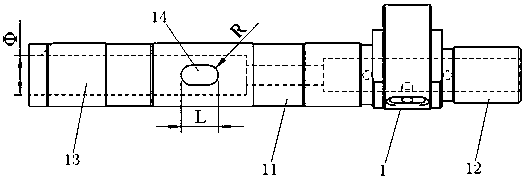
[0012] like figure 1 As shown, the crankshaft structure of the present invention that reduces the oil circulation rate of the rolling rotor compressor includes a crankshaft body 1, and the crankshaft body 1 includes a long axis section 11 and a short axis section 12, and the long axis section 11 of the crankshaft body 1 is along the axis A central exhaust hole 13 is provided in the direction, and the long axis section 11 of the crankshaft body 1 is provided with a transverse through hole 14 communicating with the central exhaust hole 13 in the radial direction.

[0013] In this crankshaft structure, a central exhaust hole is provided in the axial direction on the long axis section of the crankshaft body, and at the same time, a transverse through hole connecting the central exhaust hole is opened in the radial direction, so that the air flow is exhausted from the horizontal through hole in the long axis section of the crankshaft body and the center of the long axis section. Th...


PUM


Abstract

The invention discloses a crankshaft structure for reducing the oil circulation rate of a rolling rotor compressor, that is, the crankshaft structure includes a crankshaft body, the crankshaft body includes a long axis section and a short axis section, and the long axis section of the crankshaft body is along the axis A central exhaust hole is arranged in the direction, and the long axis section of the crankshaft body is provided with a transverse through hole communicating with the central exhaust hole in the radial direction. The crankshaft structure effectively reduces the oil circulation rate of the compressor at high speed, ensures the cooling / heating capacity of the system at high speed, thereby improving the system matching ability of the compressor.

Description

technical field [0001] The invention relates to a crankshaft structure for reducing the oil circulation rate of a rolling rotor compressor. Background technique [0002] When the rolling rotor compressor is matched with the system, it often occurs that the power only increases at high speed, but the cooling / heating capacity does not increase accordingly. The reason is that the high oil circulation rate of the compressor at high speed reduces the heat transfer of the system. ability, leading to a decrease in system matching performance. [0003] The influence of compressor oil circulation rate on system matching performance has become a key technology in compressor competition. Effectively reducing the oil circulation rate at high compressor speed can improve system matching performance and enhance compressor competitiveness. [0004] When the compressor is running at high speed, the airflow velocity in the lower cavity of the motor is higher than the critical velocity of mo...

Claims


Application Information

Patent Timeline
Patent Type & Authority Patents(China)
IPC IPC(8): F04C29/00F16C3/10
Inventor 黄波李媛媛王艳珍
Owner SHANGHAI HITACHI ELECTRICAL APPLIANCES CO LTD
Learn More