Multi-suction-nozzle device

A multi-suction nozzle and solenoid valve technology, which is applied to workpiece clamping devices, suction cups, connecting components, etc., can solve problems such as increased cost, decreased attractiveness, and air leakage from suction nozzles.

Inactive Publication Date: 2015-07-01
KUNDA COMP TECHKUSN +1
View PDF0 Cites 0 Cited by
  • Summary
  • Abstract
  • Description
  • Claims
  • Application Information

AI Technical Summary

Problems solved by technology

[0002] In production, suction nozzles are often used to absorb parts that need to be processed. In order to solve the problem in the prior art, one air source is provided to multiple suction nozzles for processing and production at the same time. If one of the suction nozzles is not fully absorbed, the The suction nozzle will cause air leakage, affect the attractiveness of other suction nozzles, and reduce the overall attractiveness, which is not conducive to the firm and reliable adsorption of the product, often causing the product to fall off, bringing great losses to the enterprise, and increasing the problem of material consumption. If one air source is only provided for one suction nozzle, the above problems can be avoided, but the cost will be relatively increased

Method used


Image

  • Multi-suction-nozzle device
  • Multi-suction-nozzle device

Examples


Embodiment Construction

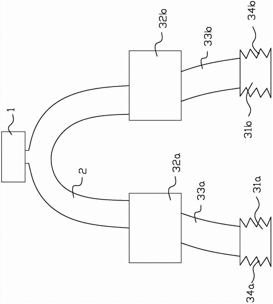
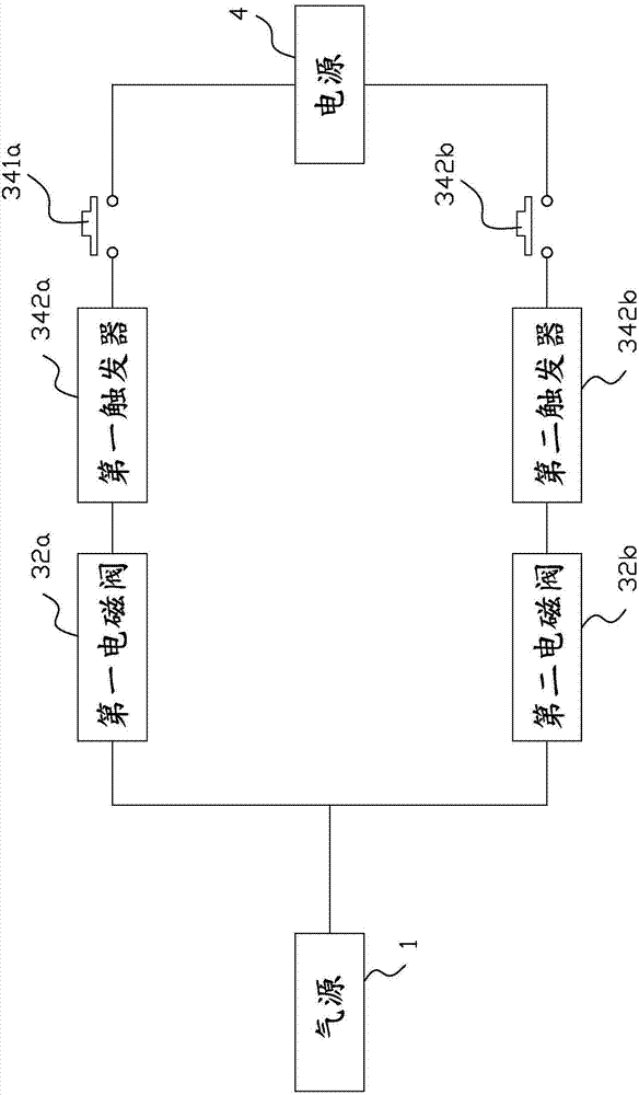
[0010] see figure 1 , figure 2 As shown, a multi-nozzle device of the present invention includes n nozzle units, an air source 1, a nozzle pipeline 2 and a power supply 4, wherein n is equal to or greater than 2, and in this embodiment, n is equal to 2, namely The nozzle unit includes a first nozzle unit and a second nozzle unit, wherein the first nozzle unit includes a first nozzle 31a, a first solenoid valve 32a, a first hose 33a, a first switch element 34a; The two-nozzle unit includes a second suction nozzle 31b, a second solenoid valve 32b, a second hose 33b, and a second switch element 34b.

[0011] The first solenoid valve 32a is connected to the air source 1 through the suction nozzle pipeline 2, the first suction nozzle 31a is connected to the first solenoid valve 32a through the first hose 33a, and the first switching element 34a includes a first A tact switch 341a and a first trigger 342a, wherein the first tact switch 341a is set on the upper corrugation or the ...


PUM


Abstract

The invention discloses a suction nozzle device. The suction nozzle device comprises n suction nozzle units, an air source, a suction nozzle pipeline and a power source, wherein n is equal to or larger than 2. The air source is connected with the suction nozzle units through the suction nozzle pipeline; each suction nozzle unit comprises a suction nozzle, an electromagnetic valve, a hose and a switch element; one end of each switch element is electrically connected with the power source, and the other end of each switch element is electrically connected with the power source end of the corresponding electromagnetic valve; the suction nozzles are connected with the electromagnetic valves through the hoses, and the electromagnetic valves are connected with the air source through the suction nozzle pipeline; and the suction nozzles are vacuum corrugated suction nozzles, and the switch elements are arranged on corrugations of the suction nozzles. The upper corrugations and the lower corrugations come into contact to press the switch elements, and the electromagnetic valves are controlled to be powered on and powered off.

Description

【Technical field】 [0001] The invention relates to a suction nozzle device, in particular to a multi-suction nozzle device. 【Background technique】 [0002] In production, suction nozzles are often used to absorb parts that need to be processed. In order to solve the problem in the prior art, one air source is provided to multiple suction nozzles for processing and production at the same time. If one of the suction nozzles is not fully absorbed, the The suction nozzle will cause air leakage, affect the attractiveness of other suction nozzles, and reduce the overall attractiveness, which is not conducive to the firm and reliable adsorption of the product, often causing the product to fall off, bringing great losses to the enterprise, and increasing the problem of material consumption. If one air source is only provided for one suction nozzle, the above problems can be avoided, but the cost will be relatively increased. The invention solves the problem that when one air source ...

Claims


Application Information

Patent Timeline
Patent Type & Authority Applications(China)
IPC IPC(8): F16B47/00
CPCB25B11/005
Inventor 许世法
Owner KUNDA COMP TECHKUSN
Why Eureka
Try Eureka