
Air conditioner and air supply structure thereof

An air conditioner and air duct technology, applied in the field of air conditioners, can solve the problems of reduced air volume, uneven air flow, and reduced wind speed, and achieve the effects of uniform air output, good air induction effect, and improved comfort.

Active Publication Date: 2015-07-01
GD MIDEA AIR-CONDITIONING EQUIP CO LTD +1
View PDF6 Cites 16 Cited by
  • Summary
  • Abstract
  • Description
  • Claims
  • Application Information

AI Technical Summary

Problems solved by technology

As the wind enters the air supply structure from the lower part, when it flows to the upper part of the air supply structure, the wind speed and air volume of the wind blown from the upper part of the air supply structure decrease, which will cause the air flow rate sent out around the wind tunnel Uneven, so needs improvement

Method used


Image

  • Air conditioner and air supply structure thereof
  • Air conditioner and air supply structure thereof
  • Air conditioner and air supply structure thereof

Examples


Embodiment Construction

[0038] Embodiments of the present invention are described in detail below, examples of which are shown in the drawings, wherein the same or similar reference numerals designate the same or similar elements or elements having the same or similar functions throughout. The embodiments described below by referring to the figures are exemplary only for explaining the present invention and should not be construed as limiting the present invention.

[0039] In describing the present invention, it should be understood that the terms "center", "longitudinal", "transverse", "length", "width", "thickness", "upper", "lower", "front", " Orientation indicated by rear, left, right, vertical, horizontal, top, bottom, inside, outside, clockwise, counterclockwise, etc. The positional relationship is based on the orientation or positional relationship shown in the drawings, which is only for the convenience of describing the present invention and simplifying the description, rather than indicati...


PUM


Abstract

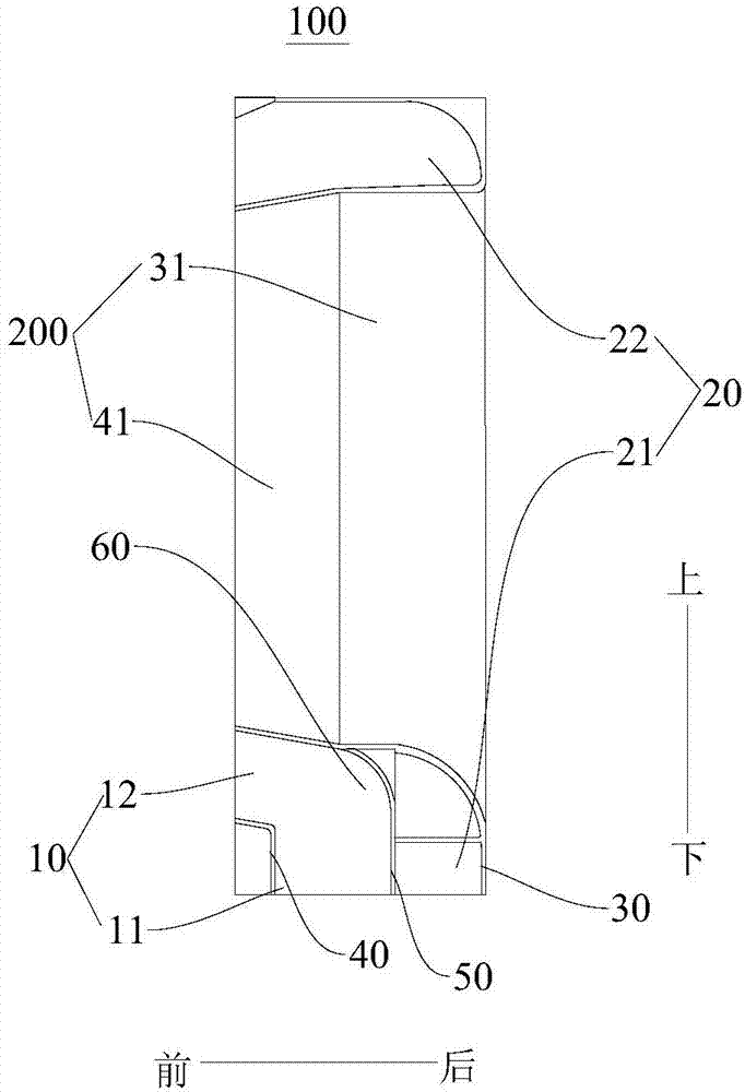
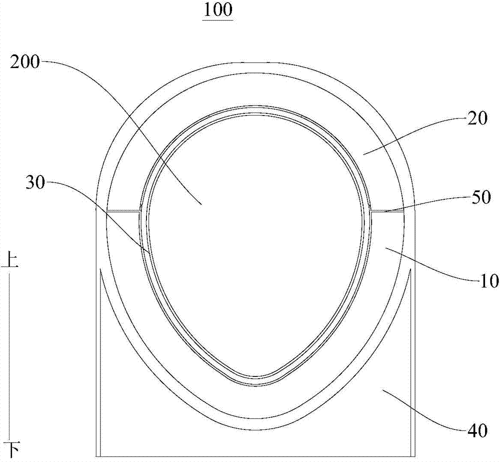
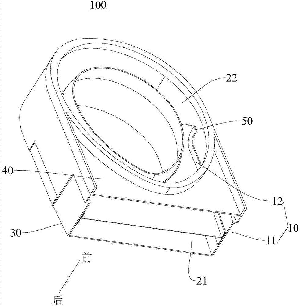
The invention discloses an air conditioner and an air supply structure thereof. The air supply structure of the air conditioner is provided with an air tunnel throughout the air supply structure in the front-back direction. The air supply structure internally comprises a plurality of air channels. The air channels are arranged in a mutually spaced mode. Each air channel is provided with an air inlet and an air outlet. The air inlets of all the air channels are formed in the bottom of the air supply structure. All the air outlets are formed in the front end of the air supply structure and surround the air tunnel. The air outlets of all the air channels are sequentially arranged in the vertical direction. According to the air supply structure of the air conditioner, supplied air is more uniform.

Description

technical field [0001] The invention relates to the field of household appliances, in particular to an air supply structure of an air conditioner and an air conditioner with the air supply structure. Background technique [0002] In the related art, in the air supply structure of the wind tunnel air conditioner, since the wind blows upward from the inside of the air conditioner body to the inside of the air supply structure, and blows forward from around the wind tunnel structure, the air behind the wind tunnel structure is guided forward. , thus forming supplementary wind. As the wind enters the air supply structure from the lower part, when it flows to the upper part of the air supply structure, the wind speed and air volume of the wind blown from the upper part of the air supply structure decrease, which will cause the air flow rate sent out around the wind tunnel Not uniform, so needs improvement. Contents of the invention [0003] The present invention aims to solve...

Claims


Application Information

Patent Timeline
Patent Type & Authority Applications(China)
IPC IPC(8): F24F13/06F24F1/00F24F13/30
CPCF24F13/02F24F13/20F24F13/30
Inventor 华龙
Owner GD MIDEA AIR-CONDITIONING EQUIP CO LTD
Learn More