Novel wind chamber enabling wind to enter in a tapered way

An air chamber and air intake technology, which is applied in the direction of combustion air/fuel supply, combustion method, combustion equipment, etc., can solve problems such as uneven air supply

Active Publication Date: 2012-09-12
DALIAN HUIYING MACHINERY
View PDF7 Cites 6 Cited by
  • Summary
  • Abstract
  • Description
  • Claims
  • Application Information

AI Technical Summary

Problems solved by technology

There is an unev

Method used


Image

  • Novel wind chamber enabling wind to enter in a tapered way
  • Novel wind chamber enabling wind to enter in a tapered way
  • Novel wind chamber enabling wind to enter in a tapered way

Examples


Embodiment Construction

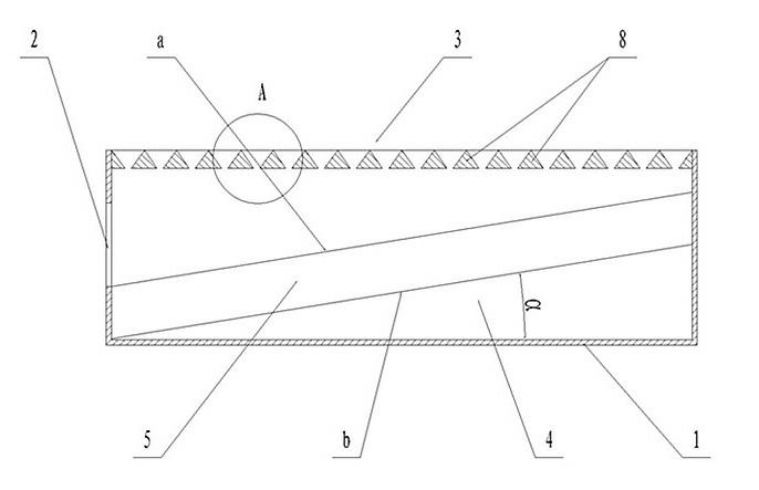
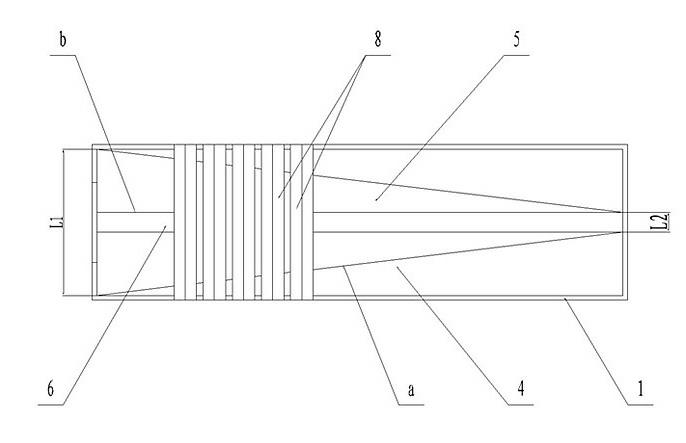
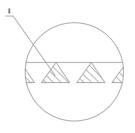
[0011] The specific implementation manner of the present invention will be described below with reference to the accompanying drawings. like figure 1 , figure 2 Shown: a new type of tapered air inlet air chamber, including the air chamber body 1, the air chamber body 1 is a cavity structure with an air inlet 2 at one end, and its upper end is an air outlet 3, inside the air chamber body 1 , along the axial direction (air inlet direction), there is an air deflector 4 obliquely upward. This air deflector 4 is composed of two sub-air deflectors 5 arranged symmetrically along the axial direction of the air chamber body 1. The two wind deflectors The lower edges of the plates 5 are parallel to each other, and a gap 6 is left between each other; the upper edges a of the two sub-air deflectors 5 are on the side close to the air inlet 2, and the distance between them is L1, and the distance between them is L1 away from each other. On one side of the air inlet 2, the distance betwee...


PUM


Abstract

The invention discloses a novel wind chamber enabling wind to enter in a tapered way. The novel wind chamber comprises a wind chamber body; a wind deflector inclining upward is arranged in the wind chamber body and consists of branch wind deflectors which are symmetrically arranged along the axial direction of the wind chamber body; lower edges b of the two branch wind deflectors are to each other; at the side near a wind inlet, the upper edges a of the two branch wind deflectors have the distance of L1 from each other, and at the side far away from the wind inlet, the upper edges a of the two branch wind deflectors have the distance of L2 from each other; an included angle alpha between the axial direction of the lower edge b of each branch wind deflector and the horizontal plane is in the range of 4-10 degrees; the wind chamber body provided with the wind deflector has a Y-shaped section, an included angle beta between two Y-shaped inclined edges and the vertical direction is in the range of 100-150 degrees; a dust collecting storage is arranged below a gap; and a plurality of wind strips are radially arranged in parallel at equival intervals at a wind outlet along the wind chamber body. According to the invention, the novel wind chamber enabling wind to enter in a tapered way is simple in structure and ingenious in design and can utilize a tapered wind deflector to enable air to be uniformly blown.

Description

technical field [0001] The invention relates to a fire grate air chamber, in particular to a tapered air intake novel air chamber capable of uniformly supplying air to the upper fire grate slices. Background technique [0002] A grate is a part of a boiler or industrial furnace that stacks solid fuel and makes it burn efficiently. The grate mainly includes two parts: the frame and the grate piece. A separate air chamber is arranged under the grate pieces so that air can be blown through the gaps between the grate pieces. The traditional air chamber structure is only a simple cube. After the air is sent in from the side of the air chamber, it is directly blown to the air outlet on the upper end of the air chamber to provide combustion aids for the fuel. During the working process of this kind of air chamber, the closer the air inlet is, the faster the air velocity is, and the fuel there gets more combustion oxidizer, while the situation farther away from the air inlet is th...

Claims


Application Information

Patent Timeline
IPC IPC(8): F23L1/02
Inventor 谢德惠徐胜利田夫辛建池王晓放
Owner DALIAN HUIYING MACHINERY
Why Eureka
Try Eureka