Ampoule machine neck compression cam

A technology of ampoule machine and cam, which is applied in the direction of measuring devices, instruments, and material analysis through optical means, which can solve the problems affecting the shape of products, the deformation of neck pressing cams, and the image of production enterprises, so as to achieve reliable and inferior products and avoid inferior quality The effect of the product

Inactive Publication Date: 2015-07-01
SHANDONG PHARMA GLASS
View PDF0 Cites 0 Cited by
  • Summary
  • Abstract
  • Description
  • Claims
  • Application Information

AI Technical Summary

Problems solved by technology

[0002] During the pressing process of the existing ampoules, sometimes there will be cracks in the neck, and it is not easy to be detected when the production line is used for production. After such ampoules are sold to the market, it will greatly affect the image of the manufacturer. During the use of the cam, the pressure neck cam will deform as time goes on. If the deformation is slight, it will not affect the production, but if the deformation continues to increase with time, it will not only affect the shape of the product, but also increase Cracks in the bottleneck
[0003] The defects of the current existing technology are: firstly, the ampoules with cracks in the bottleneck pressing are not easy to be detected, which greatly affects the company's image; secondly, it is impossible to know in time when the neck cam is deformed to affect product quality

Method used


Image

  • Ampoule machine neck compression cam
  • Ampoule machine neck compression cam

Examples


Embodiment 1

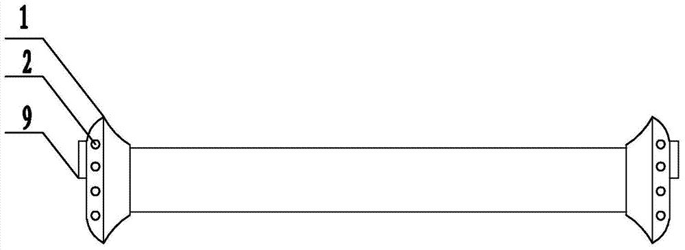
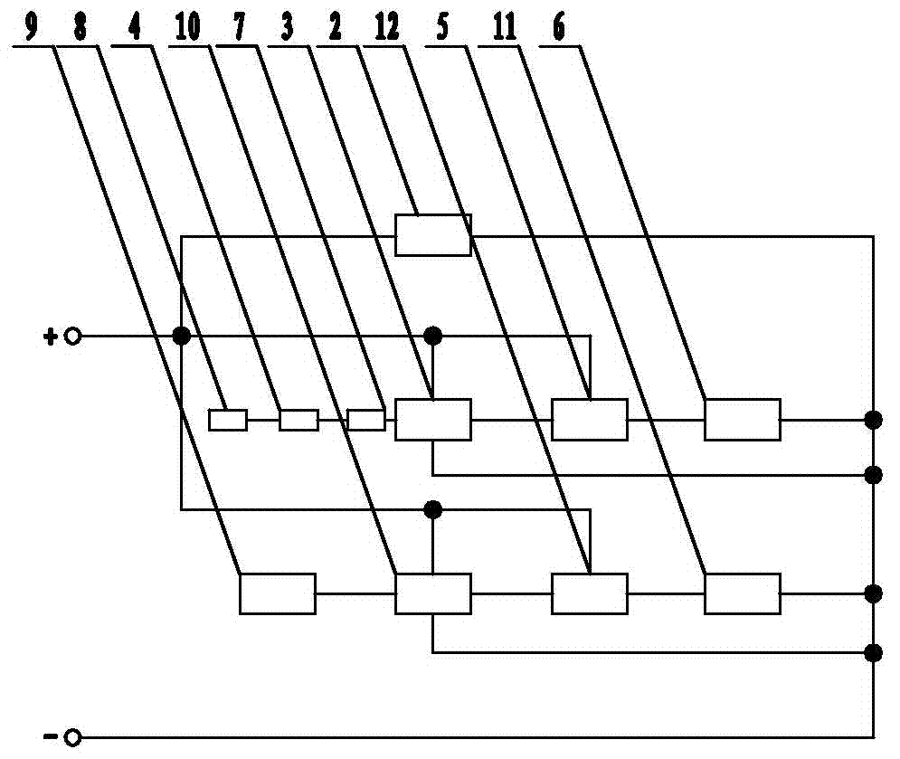
[0014] Embodiment 1: as figure 1 and figure 2 As shown, the neck pressing cam of the ampoule machine according to the present invention includes a neck pressing cam 1, which is a hollow structure, a laser light 2 is provided on the surface of the neck pressing cam 1, and a controller 3 is arranged inside the neck pressing cam 1. Photoelectric converter 4, relay 5, alarm horn 6 and analog-to-digital converter 7, a laser receiver 8 is arranged below the product pressed by the neck cam 1, and the signal output end of the laser receiver 8 is connected to the signal receiving end of the photoelectric converter 4 , the signal sending end of the photoelectric converter 4 is connected to the analog-to-digital converter 7, the signal sending end of the analog-to-digital converter 7 is connected to the signal receiving end of the controller 3, the laser light 2 and the controller 3 are connected to the power supply through the air switch, and the alarm horn 6 The power terminal of the...

Embodiment 2

[0015] Embodiment 2: On the basis of the structure of Embodiment 1, the neck-pressing cam of the ampoule machine is provided with a distance sensor 9 at both ends of the neck-pressing cam 1, and a bulb 11, a contactor 12 and a distance sensor 9 are arranged inside the neck-pressing cam 1. In the controller 10, the output end of the distance sensor 9 is connected to the input end of the distance controller 10, the output end of the distance controller 10 is connected to the control end of the contactor 12, and the bulb 11 is connected to the power supply through the power end of the contactor 12.

[0016] Operation steps and working principle:

[0017] When the ampoule produced has no cracks, the optical power of the laser lamp 2 received by the laser receiver 8 is constant, but when there are cracks or bubbles, the laser is affected by the refraction of the cracks or bubbles, and the power will change greatly and continuously. After the signal is converted by the photoelectric...


PUM


Abstract

The invention provides an ampoule machine neck compression cam and belongs to the field of ampoule machine neck compression cams. The ampoule machine neck compression cam comprises a neck compression cam body which is in a hollow structure. Laser lamps are arranged in the neck compression cam body. A controller, a photoelectric transducer, a relay, an alarm horn and an analog-digital converter are arranged in the neck compression cam body. A laser receiver is arranged below a produced compressed by the neck compression cam body, the signal output end of the laser receiver is connected with the signal receiving end of the photoelectric transducer, the signal sending end of the photoelectric transducer is connected with the analog-digital converter, the signal sending end of the analog-digital converter is connected with the signal receiving end of the controller, the laser and the controller are both connected with a power supply through an air switch, the alarm horn is connected with the power supply through the relay power end, and the signal input end of the controller is connected with the relay control end. By means of the cam, cracks of ampoule machine necks can be detected and alarmed, and indication lamps can be turned on when neck compression cams deform and affect the product quality.

Description

technical field [0001] The invention provides a neck pressing cam of an ampoule machine, which belongs to the field of neck pressing cams of an ampoule machine. Background technique [0002] During the pressing process of the existing ampoules, sometimes there will be cracks in the neck, and it is not easy to be detected when the production line is used for production. After such ampoules are sold to the market, it will greatly affect the image of the manufacturer. During the use of the cam, the pressure neck cam will deform as time goes on. If the deformation is slight, it will not affect the production, but if the deformation continues to increase with time, it will not only affect the shape of the product, but also increase The situation where the bottleneck suppresses cracks. [0003] The defects of the current existing technology are: firstly, the ampoules with cracks in the bottleneck pressing are difficult to be detected, which greatly affects the company's image; se...

Claims


Application Information

Patent Timeline
IPC IPC(8): G05B19/06
CPCG01N21/958
Inventor 张军王法利毕研祯李志刚
Owner SHANDONG PHARMA GLASS
Why Eureka
Try Eureka