
Batch stamping equipment for outer chain plates of chains

A technology for stamping equipment and outer chain plates, which is applied in shearing machine equipment, welding equipment, metal chains, etc., can solve the problem that the edges of the outer chain plates cannot be polished smoothly, the outer chain plates cannot be accurately produced, and the outer chain plates cannot be improved. Quality and other issues, to avoid the generation of burrs and tiny cracks, realize the dual functions of punching and cutting, and reduce the space occupied

Pending Publication Date: 2021-12-07
无锡市满诚链传动制造有限公司
View PDF0 Cites 0 Cited by
  • Summary
  • Abstract
  • Description
  • Claims
  • Application Information

AI Technical Summary

Problems solved by technology

[0004] The purpose of the present invention is to provide a batch punching equipment for chain outer chain plates to solve the problem that most of the stamping equipment on the market in the background technology cannot accurately produce chain outer connecting plates, and burrs are prone to appear in the production process, which cannot improve the outer chain. The quality of the board, the problem of not being able to smooth the edges around the outer chain board

Method used


Image

  • Batch stamping equipment for outer chain plates of chains
  • Batch stamping equipment for outer chain plates of chains
  • Batch stamping equipment for outer chain plates of chains

Examples


Embodiment Construction

[0018] The following will clearly and completely describe the technical solutions in the embodiments of the present invention with reference to the accompanying drawings in the embodiments of the present invention. Obviously, the described embodiments are only some, not all, embodiments of the present invention. Based on the embodiments of the present invention, all other embodiments obtained by persons of ordinary skill in the art without making creative efforts belong to the protection scope of the present invention.

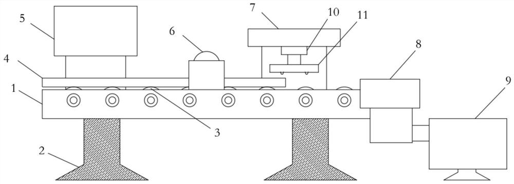
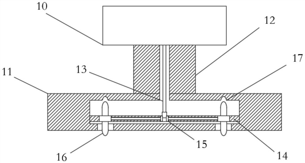
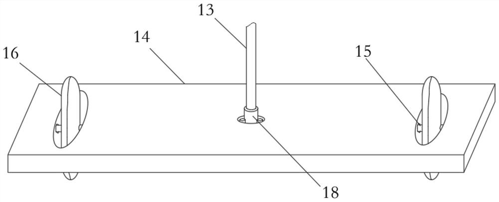
[0019] see Figure 1-4 , the present invention provides a technical solution: a batch stamping equipment for chain outer chain plates, including a transmission plate body 1, a support foot 2 is fixed on the lower end surface of the transmission plate body 1, and a transmission roller 3 is installed inside the transmission plate body 1 A steel plate raw material 4 is placed on the upper surface of the conveying roller 3, a laser cutting machine 5 is arranged on...


PUM


Abstract

The invention discloses batch stamping equipment for outer chain plates of chains. The batch stamping equipment for outer chain plates of chains comprises a conveying plate body, a hydraulic cylinder is arranged on the portion, close to the right side, of the upper end surface of the conveying plate body, a grinding main body is installed on the right end surface of the conveying plate body, the right end of the grinding main body is connected with a collecting box, and a motor is installed in the middle of the lower end surface of the hydraulic cylinder, supporting legs are fixedly arranged on the surface of the lower end of the conveying plate body, conveying rollers are installed in the conveying plate body, steel plate raw materials are placed on the surfaces of the upper ends of the conveying rollers, a laser cutting machine is arranged on the surface, close to the upper side, of the rear end of the conveying plate body, and a feeding roller is arranged on the surface, close to the middle position, of the upper end of the conveying plate body. According to the batch stamping equipment for outer chain plates of chains, the outer chain plates of chains can be accurately manufactured, burrs and tiny cracks can be effectively avoided, the quality of the outer chain plates is improved, the peripheral edge of the outer chain plates is effectively polished to be smooth, and poor-quality products are avoided.

Description

technical field [0001] The invention relates to the technical field of stamping of outer chain plates, in particular to batch stamping equipment for chain outer chain plates. Background technique [0002] The outer chain plate of the chain is mainly used in the cooling and transportation of glass products and castings, or the use of chain crawler equipment in domestic transportation equipment, and the discharge and transportation of machined iron filings, and can also transport various metal products, such as stamping waste Or all kinds of metal processing parts, with the characteristics of large load capacity and durability; [0003] Most of the stamping equipment on the market cannot accurately produce chain outer plates, burrs are prone to appear in the production process, the quality of the outer chain plates cannot be improved, and the edges of the outer chain plates cannot be polished smoothly. Therefore, we propose a chain outer plate Chain plate batch stamping equip...

Claims


Application Information

Patent Timeline
IPC IPC(8): B21L9/02B21L9/04B23K26/38B23D19/00B24B9/04
CPCB21L9/02B21L9/04B23K26/38B23D19/00B24B9/04
Inventor 张逸成张青峰
Owner 无锡市满诚链传动制造有限公司
Learn More