Hydraulic cylinder, in particular for a clutch actuating device in a motor vehicle

A technology of motor vehicles, hydraulic cylinders, applied in the field of hydraulic cylinders

Active Publication Date: 2015-07-01
SCHAEFFLER TECH AG & CO KG
View PDF8 Cites 2 Cited by
  • Summary
  • Abstract
  • Description
  • Claims
  • Application Information

AI Technical Summary

Problems solved by technology

Simultaneous movement of at least two pistons is only possible because the piston of the hydraulic cylinder is rigidly fixed on the bearing ring of the release bearing

Method used


Image

  • Hydraulic cylinder, in particular for a clutch actuating device in a motor vehicle
  • Hydraulic cylinder, in particular for a clutch actuating device in a motor vehicle
  • Hydraulic cylinder, in particular for a clutch actuating device in a motor vehicle

Examples


Embodiment Construction

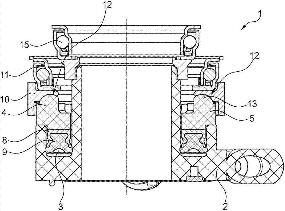
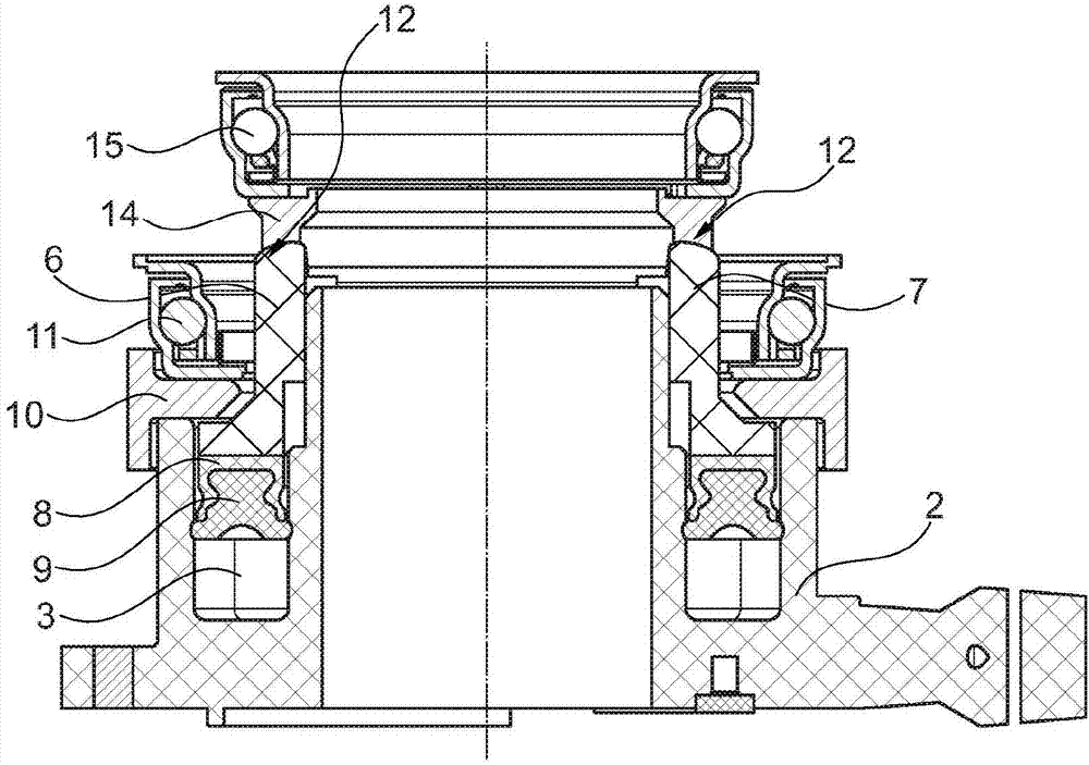
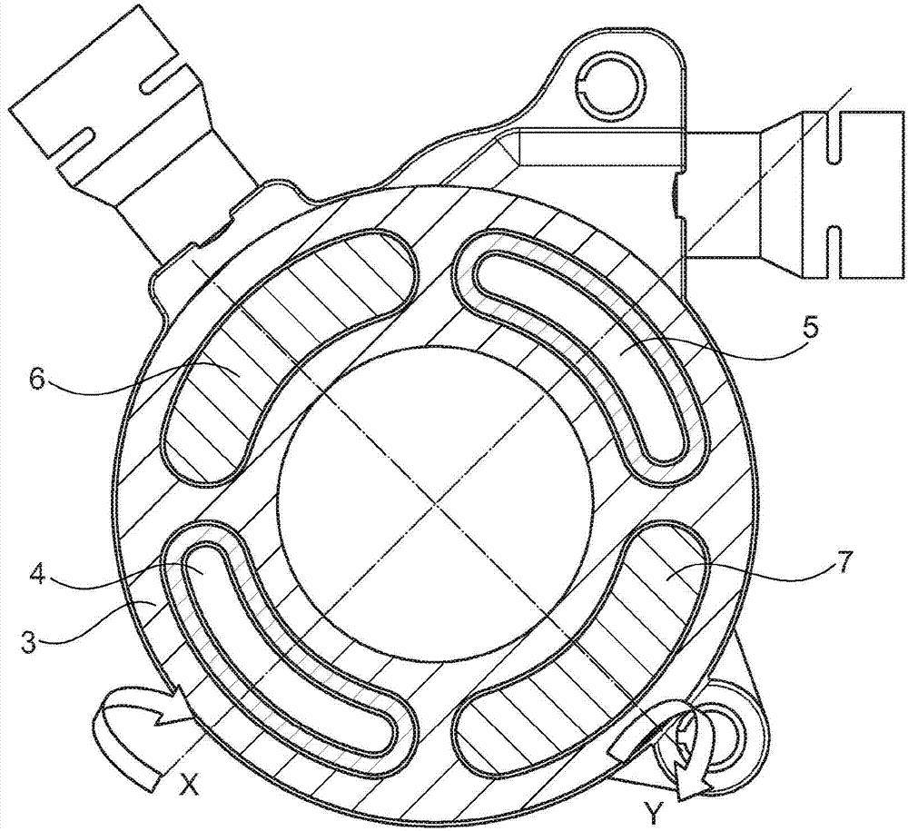
[0020] figure 1 A hydraulic cylinder 1 is shown, which is used as a slave cylinder in a clutch actuating device of a motor vehicle and is used here in particular for operating a double clutch. The hydraulic cylinder 1 consists of a housing 2, in which an annularly formed pressure chamber 3 extends, and four kidney-shaped pistons 4, 5, 6, 7 ( image 3 ) are mounted in the pressure chamber independently of each other in a movable manner. In this case, each piston 4 , 5 , 6 , 7 has a seal carrier 8 in the direction of the pressure chamber 3 , on which a seal 9 is arranged. The housing 2 surrounds a transmission shaft, not shown further.

[0021] Connected to the opposite pistons 4 and 5 is a first bearing ring 10 on which a first release bearing 11 is fixedly positioned. Release bearing 11 is connected to a first clutch, not further shown. The bearing ring 10 here has a circumferential recess 12 in which the ends of the respective pistons 4 and 5 are accommodated. The ends o...


PUM


Abstract

The invention relates to a hydraulic cylinder, in particular for a clutch actuating device in a motor vehicle, comprising a housing which is arranged concentrically around a shaft and which has an annular pressure chamber in which at least two pistons (4, 5; 6, 7) are movably mounted, wherein the pistons are connected via a bearing ring (10; 14) to a release bearing (11; 15). In the case of a hydraulic cylinder which compensates wobbling movements, the bearing ring (10; 14) of the release bearing rests in tiltable fashion on the pistons (4, 5; 6, 7).

Description

technical field [0001] The invention relates to a hydraulic cylinder, in particular a hydraulic cylinder for a clutch actuating device in a motor vehicle, comprising a housing which is arranged concentrically around a shaft and has an annular pressure chamber in which the At least two pistons are movably mounted, wherein the pistons are connected to a release bearing via bearing rings. Background technique [0002] Clutch operating devices are used in motor vehicles to separate and establish a force fit between an engine and a transmission. In this case, the slave cylinder, which is designed as a hydraulic cylinder, is moved in the hydraulic clutch actuating device in the direction of the release element, for example the clutch disc, whereby the clutch is closed. For use in multi-piston separators, the hydraulic cylinder consists of a housing which is arranged concentrically around the shaft. The housing has an annular pressure chamber, in which at least two pistons are mo...

Claims


Application Information

Patent Timeline
Patent Type & Authority Applications(China)
IPC IPC(8): F16D25/08
CPCF16D25/083F16D21/06F16D25/10F16D2021/0669
Inventor 奥拉夫·维尔纳丹尼尔·博什尼亚克吕本·克拉托夫
Owner SCHAEFFLER TECH AG & CO KG
Why Eureka
Try Eureka