Synchronous door cam device integrated with car door lock

A technology of synchronous door and integrated car, applied in transportation and packaging, elevators in buildings, etc., can solve the problems of low installation and debugging efficiency, increased failure rate, complex structure, etc., and achieve safe and reliable car door locking and simplified structure , the effect of simple structure

Active Publication Date: 2015-07-08
GUANGZHOU GUANGRI ELEVATOR IND
View PDF7 Cites 9 Cited by
  • Summary
  • Abstract
  • Description
  • Claims
  • Application Information

AI Technical Summary

Problems solved by technology

[0004] In the prior art, the door knife of the elevator and the car door lock great majority are set up separately, as the Chinese patent of CN101117870 of Chinese Patent Publication No., the title is called the invention patent application of the elevator car door lock, and it needs to carry out the door when installing. The debugging of the knife and the car door lock is not only inefficient, but also leads to an increase in the failure rate
[0005] Also ha

Method used


Image

  • Synchronous door cam device integrated with car door lock
  • Synchronous door cam device integrated with car door lock
  • Synchronous door cam device integrated with car door lock

Examples


Embodiment 1

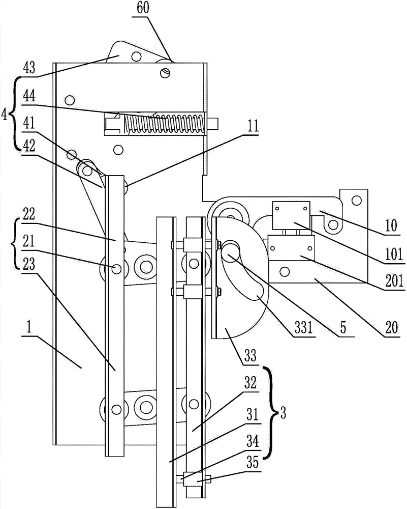
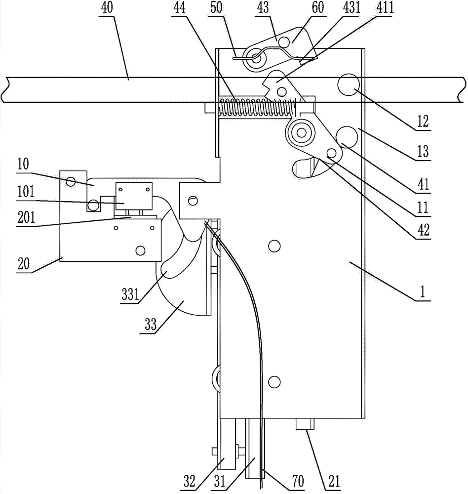
[0039] Such as Figure 1 to Figure 7 As shown, a synchronous door knife device integrating car door locks according to the present invention includes a door machine bottom plate (not shown in the figure), and a door hanging plate for hanging the car door that slides horizontally along the door machine bottom plate. A door knife bottom plate 1 is fixedly installed on the door hanging plate, and a hook seat 20 is fixed on the door machine bottom plate. The left and right inner or outer sides of the door lock roller 30 on the door knife bottom plate 1 are respectively equipped with energy clips. The moving blade swing mechanism 2 and the unlocking blade assembly 3 that hold or interfere with the door lock roller 30, the moving blade swing mechanism 2 is also connected with a transmission assembly 4, and one end of the transmission assembly 4 is hinged on the door that drives the door hanging plate to move. On the door machine transmission belt 40, the other end is hinged with the...

Embodiment 2

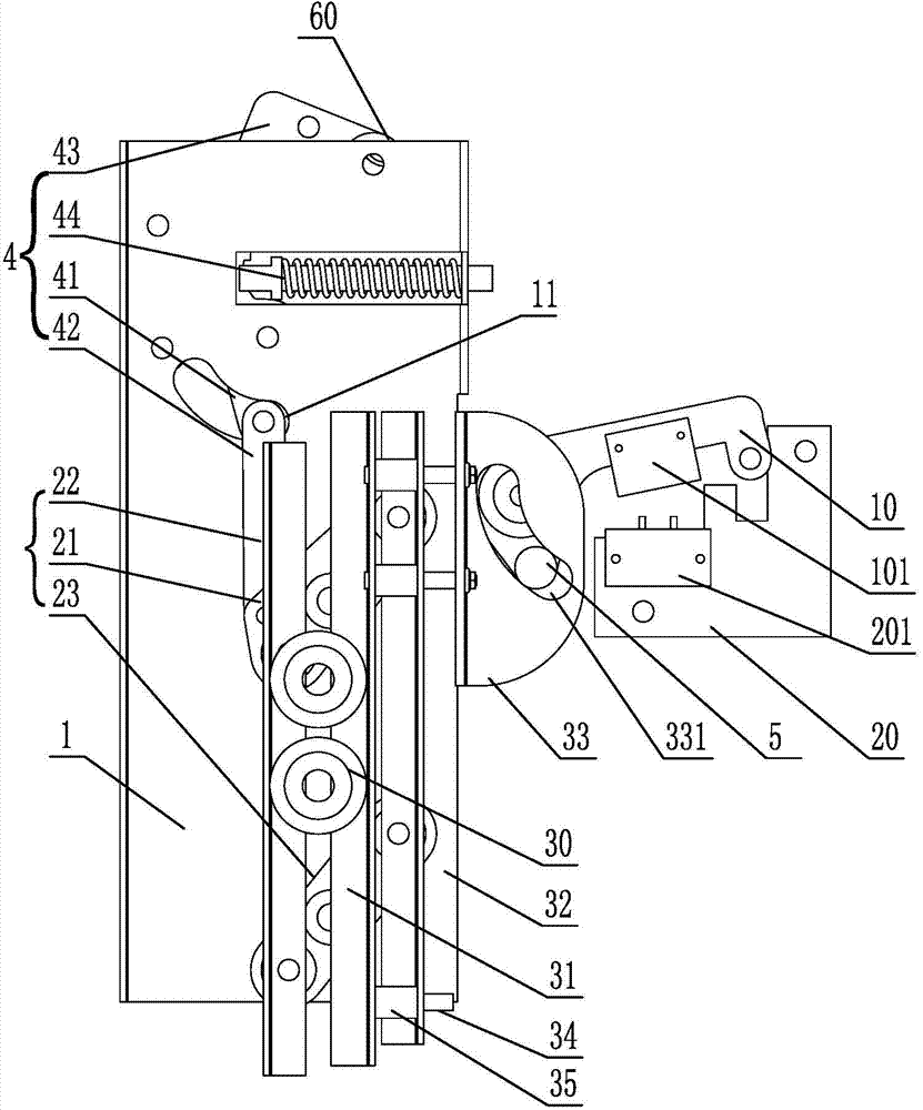
[0054] Such as Figure 8 As shown, this embodiment is basically the same as the first embodiment above, the difference is that: the two floor door lock rollers 30 are located on both sides of the moving blade 21 and the unlocking blade 31, and the limit block 32 is located between the moving blade 21 and the unlocking blade 31. Between, its operation principle is the same as that of the above-mentioned embodiment, and will not be repeated here.

Embodiment 3

[0056] Such as Figure 9 As shown, this embodiment is basically the same as Embodiment 1, the difference is that: the bottom plate of the locking hook 10 is provided with an arc-shaped track edge 102, and the unlocking end on the unlocking blade 31 is an unlocking lever 5'. In addition, A conflicting pulley can also be set on the unlocking lever 5' to achieve the purpose of unlocking. The operation principle of this implementation manner is basically the same as that of the above-mentioned embodiment, and will not be repeated here.


PUM


Abstract

The invention discloses a synchronous door cam integrated with a car door lock. The synchronous door cam provides a door machine bottom plate, and a door hanging plate which horizontally slides along the door machine bottom plate and is used for hanging a car door; a door cam bottom plate is fixedly mounted on the door hanging plate; a hook seat is fixed on the door machine bottom plate; a movable blade oscillating mechanism and an unlocking blade assembly are mounted on the door cam bottom plate and positioned at the left inner side and the right inner side or the left outer side or the right outer side of a landing door roller and can be used for clamping or propping the landing door lock roller; a transmission assembly is connected to the movable blade oscillating mechanism; one end of the transmission assembly is hinged on a door machine transmission belt which drives the door hanging plate to move, and while the other end of the transmission assembly is hinged to the movable blade oscillating mechanism; the movable blade oscillating mechanism links with the unlocking blade assembly, wherein the unlocking blade assembly is in match with a lock hook hinged to the door cam bottom plate and can be used for triggering the lock hook to hook or separate from a hook seat. According to the synchronous door cam device, the car door can be opened or closed simply by the landing door lock roller; a car door locking mechanism is integrated to the synchronous door cam, so that the structure of the door cam is simplified, and the difficulty at mounting and debugging can be reduced.

Description

technical field [0001] The invention relates to the field of elevator products, in particular to a synchronous door knife device with a car door locking mechanism. Background technique [0002] The popularization of the use of elevators has greatly facilitated people's lives at present, and at the same time, the safety performance of elevators is also increasingly concerned. [0003] The national standard GB7588-2003 "Safety Code for Elevator Manufacturing and Installation" stipulates in 11.2.1: the horizontal distance between the inner surface of the elevator shaft and the edge of the nearest door of the car sill, car door frame or sliding door should not be greater than 0.15m, It also stipulates that: if the car is equipped with mechanically locked doors and can only be opened in the unlocking area of ​​​​the landing door, except for the cases mentioned in 7.7.2.2, the operation of the lift shall automatically depend on the locking of the car door. And the locking of the ...

Claims


Application Information

Patent Timeline
IPC IPC(8): B66B13/18
CPCB66B13/125B66B13/185
Inventor 李密贺云朗侯应浩
Owner GUANGZHOU GUANGRI ELEVATOR IND
Why Eureka
Try Eureka