Vehicle lamp air tightness detection system

An air-tightness detection and air-tightness technology, which is applied in the direction of using liquid/vacuum degree for liquid-tightness measurement and measuring the fluid's acceleration and deceleration rate, etc., can solve the problems of insufficient environmental protection, increased investment and cost, and insufficient economy.

Active Publication Date: 2015-07-08
浙江龙鼎车业有限公司
View PDF6 Cites 1 Cited by
  • Summary
  • Abstract
  • Description
  • Claims
  • Application Information

AI Technical Summary

Problems solved by technology

However, the lamp needs to be fixed during the inspection. The air inlet gun and pressure gauge of the air tightness testing machine need to be aligned with the air inlet and pressure measuring port on the lamp respectively. Other air outlet holes on the lamp also need to be sealed. In order to ensure that the air intake gun will not leak air when it supplies air to the lights, but different types of lights have different shapes and sizes, and the positions of the air inlet, pressure measuring port and air outlet are also different, and the existing fixture , intake guns, pressure gauges or plugs are all set on fixed equipment, which can only be adapted to a certain type of car lights, so that each type of car lights must make new fixed equipment, which not only increases the investment and cost, not economical enough, a waste of resources, not environmentally friendly

Method used


Image

  • Vehicle lamp air tightness detection system
  • Vehicle lamp air tightness detection system
  • Vehicle lamp air tightness detection system

Examples


Embodiment Construction

[0031] Referring to the accompanying drawings, the vehicle lamp air tightness detection system includes an air tightness detection machine and a fixing device for positioning the vehicle light;

[0032] The air tightness testing machine includes an air inlet gun 5 and a pressure gauge 6, the air inlet gun 5 communicates with the air inlet of the vehicle lamp, the pressure gauge 6 communicates with the pressure measuring port of the vehicle lamp, and the The pressure measuring device 6 is provided with a sensor for measuring the air pressure value in the lamp, and the sensor is connected to a controller with a pre-stored maximum value of the air pressure difference. The controller is located in the air tightness detector, and the controller The output terminal of the sensor is connected with the display device and the warning device, and the sensor transmits the air pressure information in the lamp to the controller, and the controller controls the display device and the warning...


PUM


Abstract

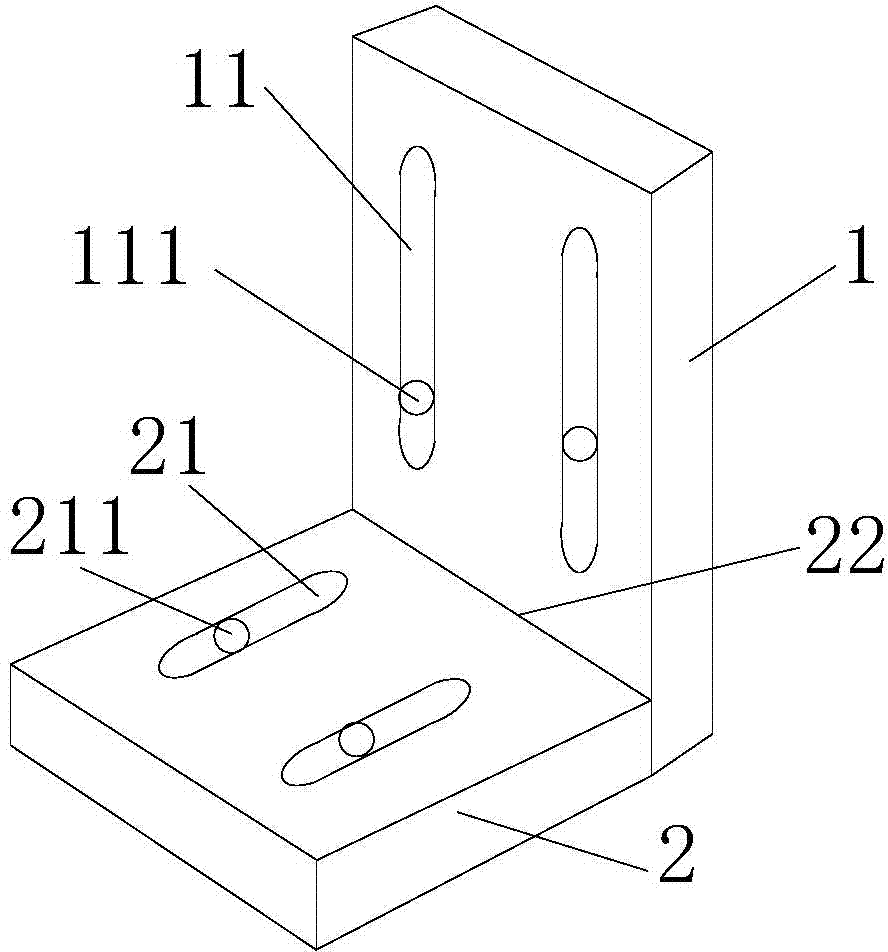
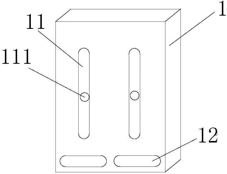
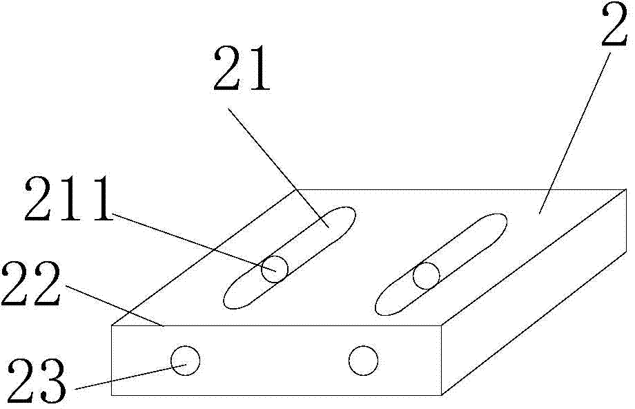
The invention discloses a vehicle lamp air tightness detection system. The vehicle lamp air tightness detection system comprises an air tightness detection machine and a fixing device; an air inlet gun is communicated with an air inlet of a vehicle lamp, and a pressure detector is communicated with a pressure detection port of the vehicle lamp; a spacer is arranged on a baseboard, the air inlet gun and the pressure detector are arranged on the periphery of the spacer, and a fixture and a plug are also arranged on the periphery of the spacer; the air inlet gun, the pressure detector, the fixture and the plug are each arranged on the corresponding support; a horizontal substrate of the supports is laid on the baseboard, and a vertical substrate of the supports is vertically arranged on the baseboard; one side edge of the horizontal substrate is closely attached to the bottom of the vertical substrate, and a first groove extending in the x axis direction is formed in the horizontal substrate; a second groove extending in the y axis direction is formed in the bottom of the vertical substrate, a second bolt is arranged on the side face, where the side edge is located, of the horizontal substrate, and the second bolt is arranged on the second groove in a penetrating mode; a third groove extending in the z axis direction is formed in the vertical substrate, and a third bolt is arranged in the third groove in a penetrating mode; an inserting hole matched with the first bolt is formed in the baseboard.

Description

technical field [0001] The invention relates to a vehicle lamp air tightness detection system. Background technique [0002] As an indispensable part of a car, car lights play the role of night lighting, traffic signals, and anti-collision in bad weather. However, due to factors such as materials and craftsmanship, car lights have airtightness problems such as gaps and leakage. Affect the function of the lights. To this end, we need to strengthen the detection of the airtightness of the lights. At present, many car lamp companies will use the air tightness testing machine to test the car lights. The air tightness testing machine will deliver gas to the car lights, and judge the airtightness of the car lights by detecting whether the car lights are leaking. However, the lamp needs to be fixed during the inspection. The air inlet gun and pressure gauge of the air tightness testing machine need to be aligned with the air inlet and pressure measuring port on the lamp respectiv...

Claims


Application Information

Patent Timeline
IPC IPC(8): G01M3/26
Inventor 何米增
Owner 浙江龙鼎车业有限公司
Why Eureka
Try Eureka