Dimming LED constant-current driving circuit

A technology of constant current drive and LED lamp group, which is applied in the direction of electric lamp circuit layout, light source, electric light source, etc., and can solve the problems of inability to adjust output power, inconvenience for users, and inability to adjust light intensity.

Inactive Publication Date: 2015-07-08
SHENZHEN OCEANS KING LIGHTING ENG CO LTD +1
View PDF4 Cites 0 Cited by
  • Summary
  • Abstract
  • Description
  • Claims
  • Application Information

AI Technical Summary

Problems solved by technology

At present, integrated integrated high-frequency modules are used to design LED drivers in DC low-voltage places, but these driving methods are all constant power output, and the output power cannot be adjusted, and the light intensity cannot be adjusted, which brings great inconvenience to users. serious inconvenience

Method used


Image

  • Dimming LED constant-current driving circuit
  • Dimming LED constant-current driving circuit

Examples


Embodiment Construction

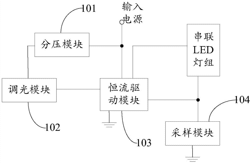
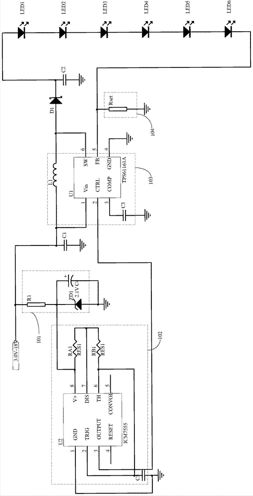
[0020] Such as figure 1 Shown is a block diagram of a dimmable LED constant current drive circuit.

[0021] A dimmable LED constant current drive circuit includes a dimming module 102 , a voltage divider module 101 , a sampling module 104 and a constant current drive module 103 .

[0022] The power supply terminal of the dimming module 102 is connected to the output terminal of the voltage divider module 101, the output terminal is connected to the enable terminal of the constant current drive module 103, and the input terminal of the voltage divider module 101 is connected to the input power supply; The power supply terminal of the constant current drive module 103 is connected to the input power supply, the ground terminal is connected to the ground, and the output terminal is connected to the positive pole of the LED lamp group connected in series, and the negative pole of the LED lamp group connected in series is connected to the output terminal of the sampling module 104,...


PUM


Abstract

A dimming LED constant-current driving circuitis used for providing working voltage for a dimming module through a voltage dividing module so as to enable the dimming module to output a pulse modulation and demodulation signal to a constant-current driving module to change the magnitude of current output by the constant-current driving module. Further, the input current of a series LED lamp group connected with the output end of the constant-current driving module can be controlled, and the lighting brightness of the series LED lamp group can be changed. A sampling module is used for sampling the current of the series LED lamp group. The constant-current driving module no longer increases the current of the series LED lamp group when the current of the series LED lamp group reaches a rated current value, so that over-current of the series LED lamp group is avoided.

Description

technical field [0001] The invention relates to an LED constant current drive circuit, in particular to a simple and easy-to-operate dimmable LED constant current drive circuit. Background technique [0002] LEDs are widely used as light sources, and various LED drive circuits have emerged accordingly. Since the LED itself has strict requirements on the working voltage, the working current of the LED will fluctuate greatly if the voltage is too high or too low, so the constant current and voltage limiting driving method is generally used for the LED. Therefore, when the LED is used as a current-type work load, the current flowing through the LED must be guaranteed to be within the rated current. At present, integrated integrated high-frequency modules are used to design LED drivers in DC low-voltage places, but these driving methods are all constant power output, and the output power cannot be adjusted, and the light intensity cannot be adjusted, which brings great inconven...

Claims


Application Information

Patent Timeline
IPC IPC(8): H05B37/02
Inventor 周明杰刘百顺
Owner SHENZHEN OCEANS KING LIGHTING ENG CO LTD
Why Eureka
Try Eureka