Rotary piston heat engine

A heat engine and rotary piston technology, applied to internal combustion piston engines, reciprocating piston engines, engines with rotating cylinders, etc., can solve problems such as low output and unfavorable cylinder rotation, and achieve cost reduction, weight reduction, and size improvement Effect

Inactive Publication Date: 2015-07-08
弗朗西斯科·哈维尔·路易斯·马丁内兹
View PDF8 Cites 0 Cited by
  • Summary
  • Abstract
  • Description
  • Claims
  • Application Information

AI Technical Summary

Problems solved by technology

Such a structure is not conducive to the rotation of the cylinder block, and has only a very low output when acting on the crankshaft, as described in patent numbers ES2072175 and ES2261007

Method used


Image

  • Rotary piston heat engine
  • Rotary piston heat engine
  • Rotary piston heat engine

Examples


Embodiment Construction

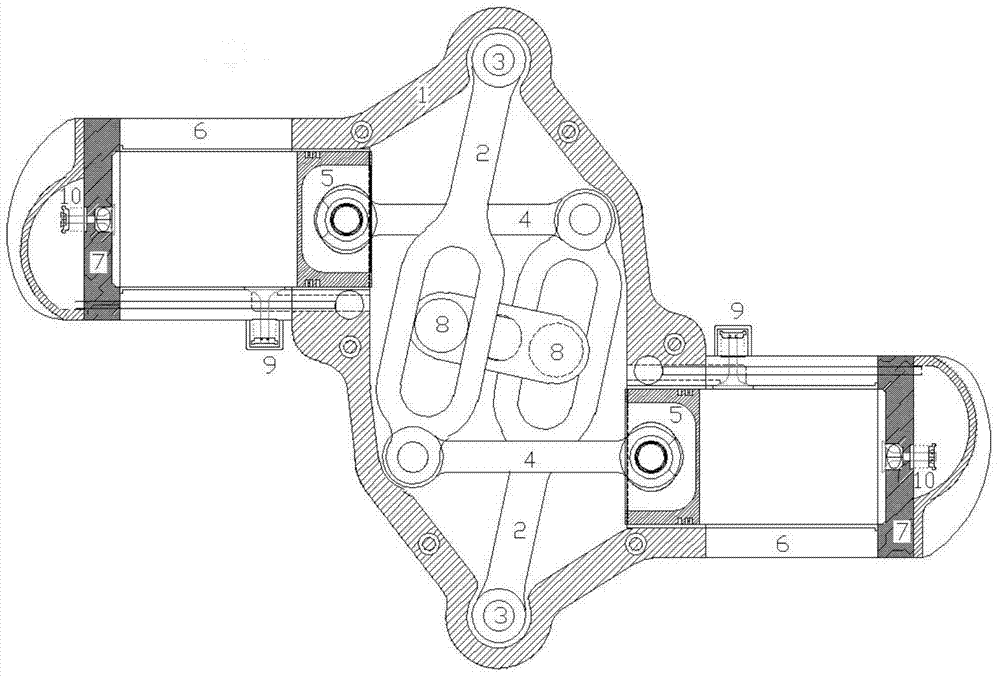
[0019] The rotary piston heat engine of the invention consists of a basic assembly formed by two casings coupled to each other. The housing houses the crankshaft and the levers that drive the pistons, and is coupled to the housing along with the cylinders and other components required for the engine to function properly.

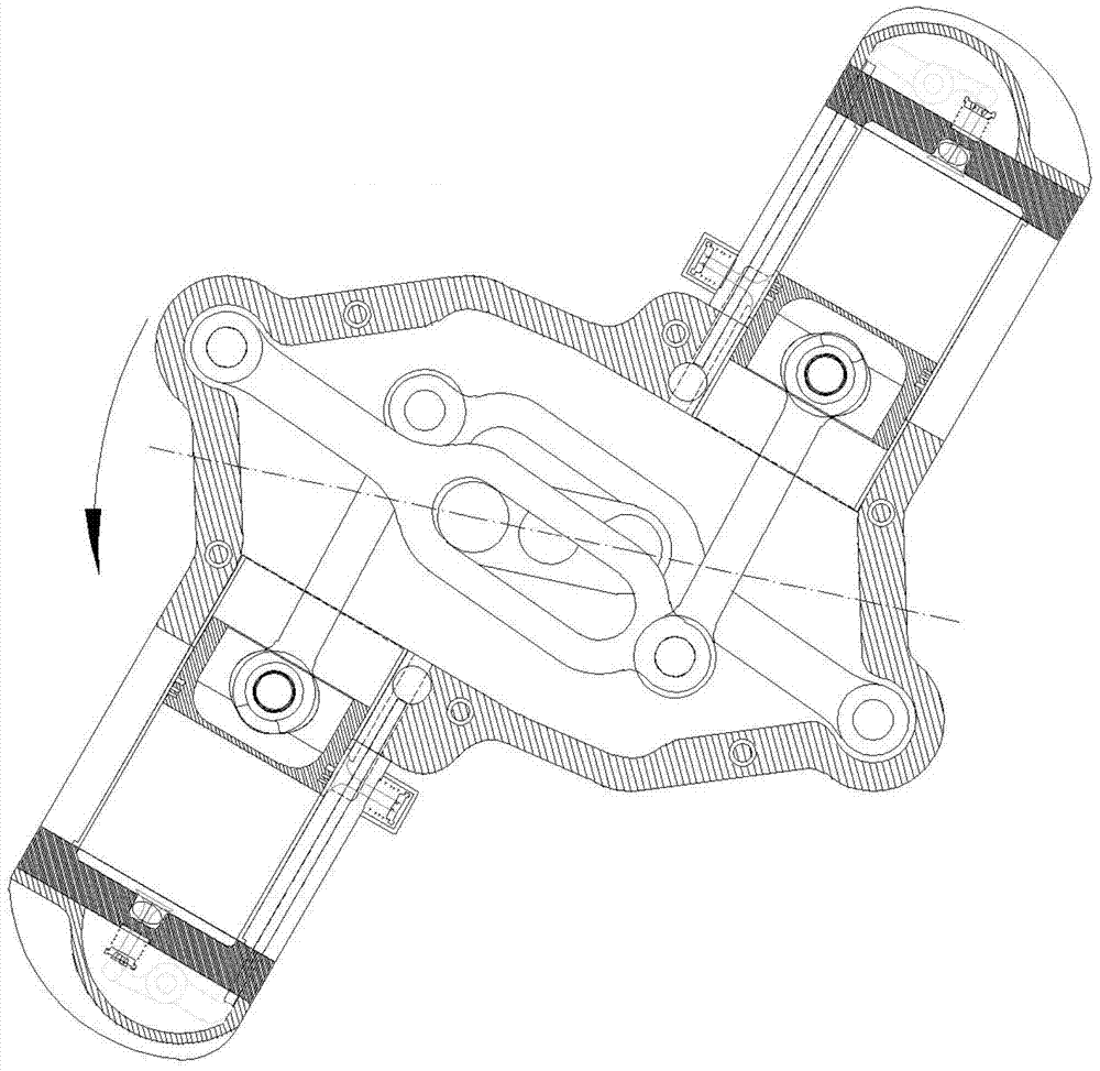
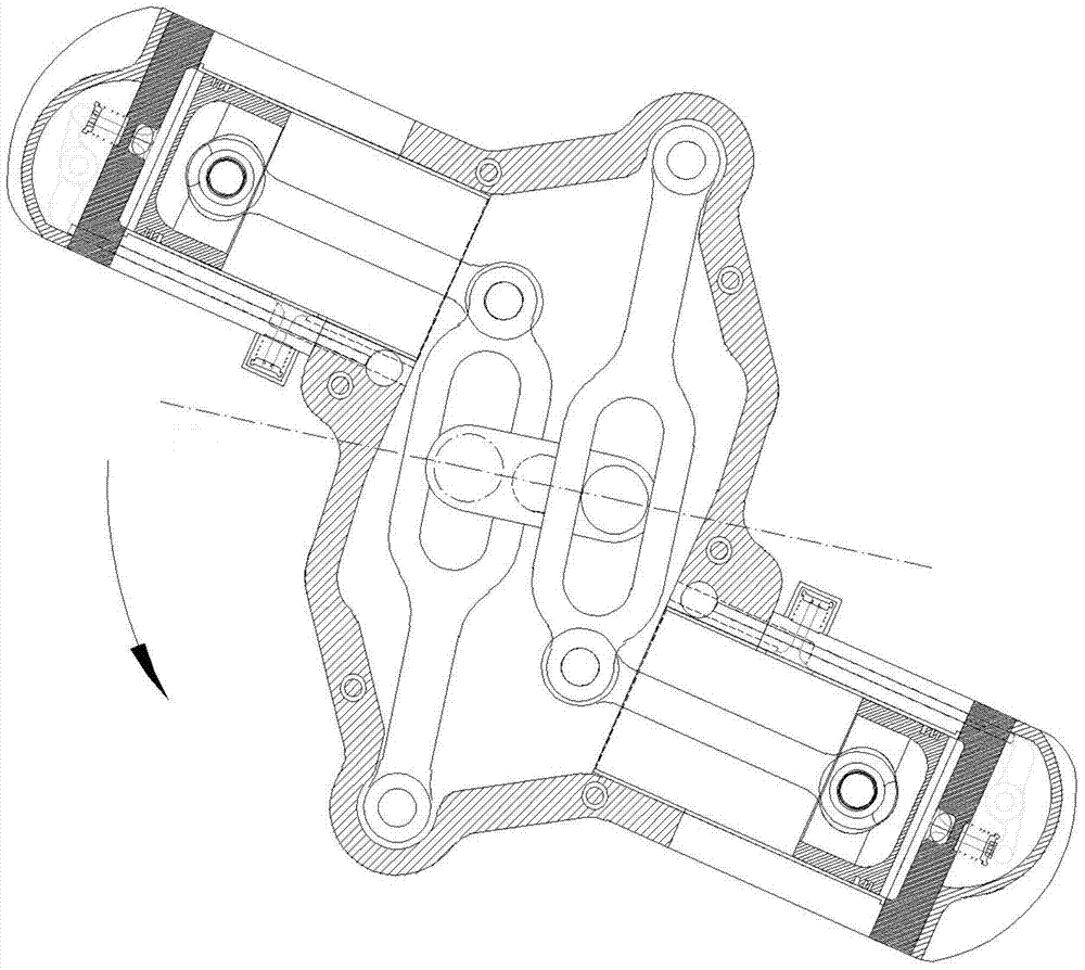
[0020] figure 1 for the floor plan. It can be seen from the figure that the lever (2) is coupled with the housing (1) through the shaft (3), and the connecting rod (4) driving the piston (5) is connected with the other end of the lever. Wherein, the connecting rod moves along the cylinder (6), and the cylinder is coupled with the cylinder head (7). The crankshaft and crank rod (8) are located in the center of the housing. Each crankshaft rod slides along the middle groove of the corresponding lever and drags the piston as the cylinder rotates. figure 2 and image 3 Shows the movement of the piston as the assembly rotates and the crankshaft remains in t...


PUM


Abstract

A rotary piston heat engine consisting of a mechanism based on a lever anchored to the periphery of a crankcase formed by two shells coupled to one another, by means of a shaft (3) located at one of the ends thereof, which enables it to pivot on the same, with an intermediate grooved portion, along which the rod of a crankshaft slides and which, with the other end, acts on a piston coupled by means of a connecting rod. The rotation of the crankcase (1) on the crankshaft (8) induces the displacement of the piston (5) coupled to the lever (2) by means of the connecting rod (4) inside the cylinder (6), the gas being compressed inside this chamber and initiating the cycle of an internal combustion engine. The shaft of the crankshaft may be blocked, thus impeding its rotation, or coupled to a single direction clutch. The basic assembly of this engine is formed by a block of two cylinders coupled to the crankcase and a crankshaft of two rods located at 180°, which act on two symmetrical levers that move both pistons.

Description

technical field [0001] The present invention relates to the general field of industrial technology, more specifically, to the transportation industry. Background technique [0002] Heat engines are generally well known and therefore will not be described here. Although several proposals for the development of rotary tangential piston engines exist, none of these proposals have been realized so far. The reason for this is that these solutions are based on the actuation of levers constructed on the two arms, resulting in low efficiency of these designs. One of the arms is provided with a groove, and the crank rod slides along the groove, and when rotating around the intermediate shaft, the arm causes a linear movement in the piston, and the piston is coupled to the other arm through a connecting rod. Ends. Such a structure is not conducive to the rotation of the cylinder block, and has only a very low output when acting on the crankshaft, as described in patent numbers ES20...

Claims


Application Information

Patent Timeline
Patent Type & Authority Applications(China)
IPC IPC(8): F01B13/04F01B9/02F01B5/00F02B75/26
CPCF01B13/04F02B75/26F02B53/02F01B9/02F01B5/00
Inventor 弗朗西斯科·哈维尔·路易斯·马丁内兹
Owner 弗朗西斯科·哈维尔·路易斯·马丁内兹
Why Eureka
Try Eureka