Speed changer, power transmission system and vehicle

A power transmission system and transmission technology, applied in the field of vehicles, can solve the problems of fewer transmission modes, low transmission efficiency, single charging mode, and single charging path, and achieve the effect of enriching transmission modes

Active Publication Date: 2015-07-15
BYD CO LTD
View PDF5 Cites 118 Cited by
  • Summary
  • Abstract
  • Description
  • Claims
  • Application Information

AI Technical Summary

Problems solved by technology

[0003] However, in the relevant technologies known to the inventor, the transmissions in hybrid vehicles are generally complex in structure, with few transmission modes and low transmission efficienc

Method used


Image

  • Speed changer, power transmission system and vehicle
  • Speed changer, power transmission system and vehicle
  • Speed changer, power transmission system and vehicle

Examples


Embodiment 1

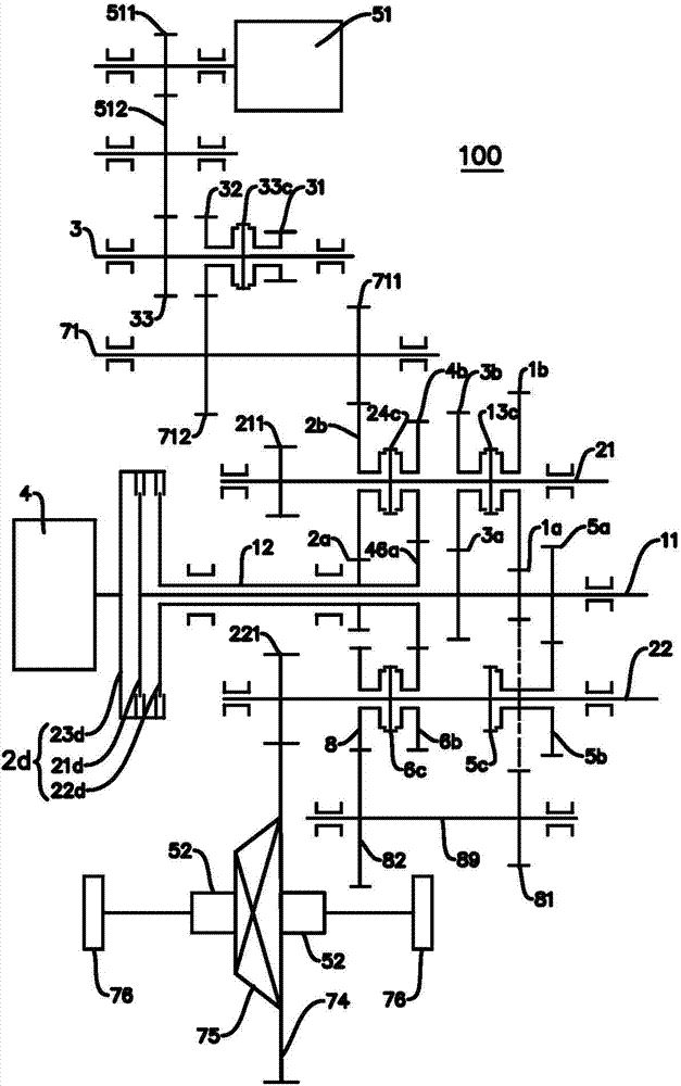
[0162] Such as figure 1As shown, the engine 4 is connected with the input end 23d of the double clutch 2d, the first output end 21d of the double clutch 2d is connected with the first input shaft 11, the second output end 22d of the double clutch 2d is connected with the second input shaft 12, and the double clutch 2d is connected with the second input shaft 12. The input end 23d of the clutch 2d and the first output end 21d and the second output end 22d of the double clutch 2d can be in disconnected state at the same time, or the input end 23d of the double clutch 2d can be connected with the first output end 21d and the second output end 21d of the double clutch 2d. One of the two output terminals 22d is engaged, or the input terminal 23d of the dual clutch 2d can be simultaneously engaged with the first output terminal 21d and the second output terminal 22d of the dual clutch 2d.

[0163] The second input shaft 12 is a hollow shaft structure, the first input shaft 11 is a s...

Embodiment 2

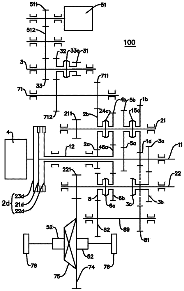
[0203] Such as figure 2 As shown, the power transmission system 100 in this embodiment and figure 1 The main difference of the power transmission system 100 shown in is the arrangement of the fifth-speed gear pair and the third-speed gear pair. Gear 3b is vacantly sleeved on the second output shaft 22, and the remaining parts are connected with figure 1 The embodiments are basically the same and will not be repeated here.

Embodiment 3

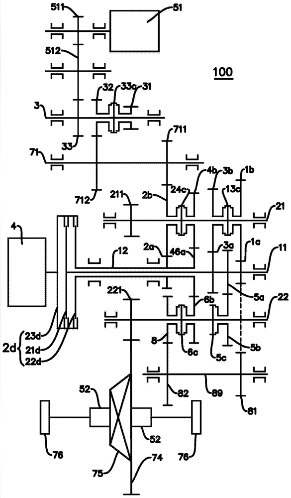
[0205] Such as image 3 As shown, the power transmission system 100 in this embodiment and figure 1 The main difference of the power transmission system 100 shown in is the position of the fifth-speed driving gear 5a and the first-speed driving gear 1a, in this embodiment, the fifth-speed driving gear 5a is located between the first-speed driving gear 1a and the third-speed driving gear 3a , and the rest with figure 1 The embodiments are basically the same and will not be repeated here.


PUM


Abstract

The invention discloses a speed changer, a power transmission system and a vehicle. The speed changer comprises a plurality of input shafts, a plurality of output shafts, a reverse gear shaft and a motor power shaft, wherein the input shafts and the output shafts are transmitted through gears; a reverse gear output gear sleeves on one of the output shafts in an idling mode, and a reverse gear synchronizer is further arranged on the output shaft; the reverse gear shaft is linked with one of the input shafts, and is also linked with the reverse gear output gear; a first gear and a second gear of the motor power shaft sleeve on the motor power shaft in an idling mode; a motor power shaft synchronizer is further arranged on the motor power shaft; the second gear of the motor power shaft is arranged to be linked with one of gear driven gears. According to the speed changer for the vehicle disclosed by the embodiment of the invention, transmission modes are enriched, and various working conditions such as parking charging and charging for an engine while driving can be realized.

Description

technical field [0001] The invention relates to the technical field of vehicles, in particular to a transmission, a power transmission system with the transmission, and a vehicle with the power transmission system. Background technique [0002] With the continuous consumption of energy, the development and utilization of new energy vehicles has gradually become a trend. As one of the new energy vehicles, a hybrid vehicle is driven by an engine and / or an electric motor, and has multiple modes, which can improve transmission efficiency and fuel economy. [0003] However, in the relevant technologies known to the inventor, the transmissions in hybrid vehicles generally have complex structures, few transmission modes, and low transmission efficiency. For example, for most hybrid electric vehicles, the charging process is often implemented during driving, the charging mode and charging path are relatively single, and the charging efficiency is poor. Contents of the invention ...

Claims


Application Information

Patent Timeline
IPC IPC(8): B60K6/36B60K6/547
CPCF16H2003/0931B60K1/02B60K6/448B60K6/48B60K6/52B60K6/547B60K2006/4841B60K17/356B60K6/36F16H3/006F16H2003/0822Y10S903/909Y10S903/911Y10S903/912Y10S903/915Y02T10/62B60K6/365B60K6/38B60K6/40B60Y2304/00B60Y2400/428B60Y2400/70B60Y2400/80F16H3/085F16H37/0806
Inventor 张金涛华煜柴领道穆金辉刘静
Owner BYD CO LTD
Why Eureka
Try Eureka