Light emitting device control circuit and control method thereof

A technology for light-emitting elements and control circuits, which is applied in the directions of electrical components, lamp circuit layout, light sources, etc., and can solve problems such as reducing brightness changes.

Inactive Publication Date: 2015-07-15
RICHTEK TECH
View PDF7 Cites 2 Cited by
  • Summary
  • Abstract
  • Description
  • Claims
  • Application Information

AI Technical Summary

Problems solved by technology

[0004] In the prior art, usually the unit time T is already the limit of the hardware and cannot be shortened any further. Therefore, to increase the refresh rate, the only way to shorten the time is to shorten the time by one period. However, in this way, the number of N must be reduced, resulting in a reduction in brightness changes. , that is to say, in the existing technology, increasing the refresh rate will sacrifice the brightness change, and increasing the refresh rate must sacrifice the refresh rate

Method used


Image

  • Light emitting device control circuit and control method thereof
  • Light emitting device control circuit and control method thereof
  • Light emitting device control circuit and control method thereof

Examples


Embodiment Construction

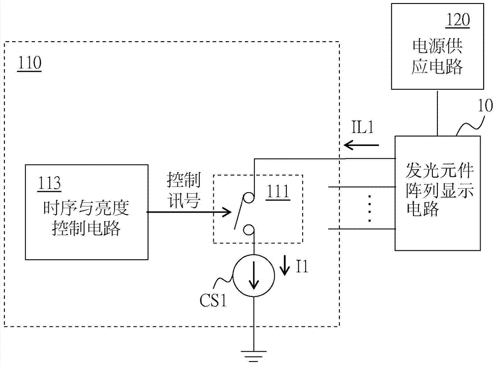
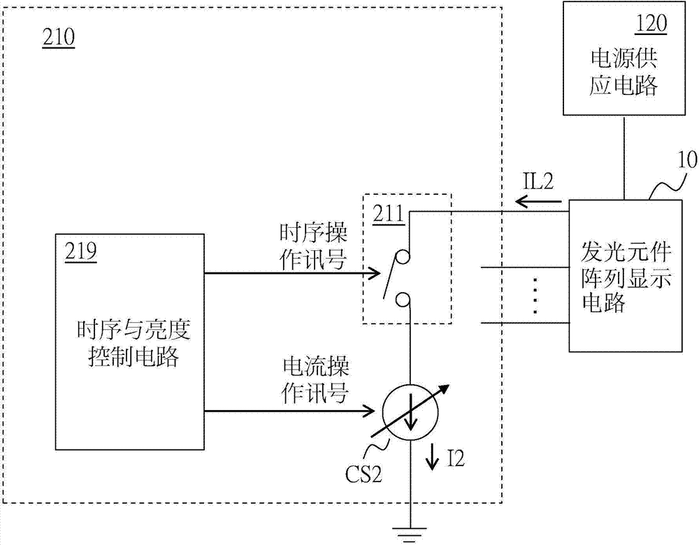
[0046] see Figures 2A-2G , showing a first embodiment of the present invention. Figure 2A A schematic diagram of a light emitting element control circuit 210 according to the first embodiment of the present invention is shown, wherein the light emitting element control circuit 210 is used to control the image and brightness of the light emitting element array display circuit 10 . like Figure 2A As shown, the power supply circuit 120 supplies power to the light-emitting element array display circuit 10, and the light-emitting element control circuit 110 determines which light-emitting elements in the light-emitting element array display circuit 10 should be turned on and illuminated, and what kind of light-emitting elements should be illuminated. brightness. To simplify the drawing, only the light-emitting element control circuit 110 is shown in the figure to control a group of light-emitting elements; in practical applications, the light-emitting element array display cir...


PUM


Abstract

The present invention discloses a light emitting device control circuit and a control method thereof, for controlling a light emitting device array display. The present invention controls not only the conduction timing and duration of one or more selected light emitting devices in the light emitting device array display, but also controls the current flowing through the selected light emitting devices by a variable current source, such that in one frame of a given length, the resolution of the brightness of the light emitting devices is increased.

Description

technical field [0001] The present invention relates to a light-emitting element control circuit and a control method, in particular to a light-emitting element control circuit and a control method capable of accelerating the refresh rate. Background technique [0002] Figure 1A A schematic diagram of a light emitting element control circuit 110 in the prior art is shown, wherein the light emitting element control circuit 110 is used to control the image and brightness of the light emitting element array display circuit 10 . like Figure 1A As shown, the power supply circuit 120 supplies power to the light-emitting element array display circuit 10, and the light-emitting element control circuit 110 determines which light-emitting elements in the light-emitting element array display circuit 10 should be turned on and illuminated, and what kind of light-emitting elements should be illuminated. brightness. To simplify the drawing, only the light-emitting element control circu...

Claims


Application Information

Patent Timeline
Patent Type & Authority Applications(China)
IPC IPC(8): H05B37/02
CPCG09G2320/064G09G3/3283G09G3/3216G09G3/2081H05B37/0281H05B45/10H05B47/16
Inventor 林建华林水木刘玓玓陈庆宇庄咏竣王钦辉杨世杰
Owner RICHTEK TECH
Why Eureka
Try Eureka