Method for reducing the refresh rate of Fiber Bragg Grating sensors

a technology of fiber bragg grating and sensor, applied in the field of improving sensors, can solve problems such as and achieve the effects of increasing the interrogation refresh rate of fgb sensors, increasing the interrogation refresh rate of fob sensors, and increasing the speed of processing information

Active Publication Date: 2014-04-15
NAT AERONAUTICS & SPACE UNITED STATES OF AMERICA AS REPRESENTED BY THE DIRECTOR OF THE
View PDF14 Cites 20 Cited by
  • Summary
  • Abstract
  • Description
  • Claims
  • Application Information

AI Technical Summary

Benefits of technology

[0011]It is a further object of this invention to provide a method of increasing the interrogation refresh rate of FGB sensors.
[0012]This invention meets these and other objectives related to improved sensors by providing a method of increasing the interrogation refresh rate of FOB sensors. Using a linearly sweep tunable laser source, a first scan of the gratings along the fibers is taken during a single sweep. This results of a raw data stream of data over a period of time. This raw data stream is divided into a plurality of segments, based on a portion of the time period. The data segments are transformed, using a Fourier Transform, resulting in frequency / grating position (GP). Each transformed segments represents the frequency content of a single time slice of the original raw data. When this data is plotted where the wavelength data is equivalent to the time to obtain the data segments, the locations of the gratings of the FOB sensors can be determined. From this information, a center of mass calculation can be performed to obtain a final reading for each grating. Because this method increases the speed of processing the information tremendously, the next scan of the gratings along the fiber may be done more quickly than using previous methods. When the method is repeated, a second set of grating location data is obtained. The change in strain can be seen by comparing the sets of data.

Problems solved by technology

While the systems described in these patents do provide certain advantages to electronic strain gauge systems, one major disadvantage relates to the interrogation refresh rate.

Method used


Image

  • Method for reducing the refresh rate of Fiber Bragg Grating sensors
  • Method for reducing the refresh rate of Fiber Bragg Grating sensors
  • Method for reducing the refresh rate of Fiber Bragg Grating sensors

Examples


Embodiment Construction

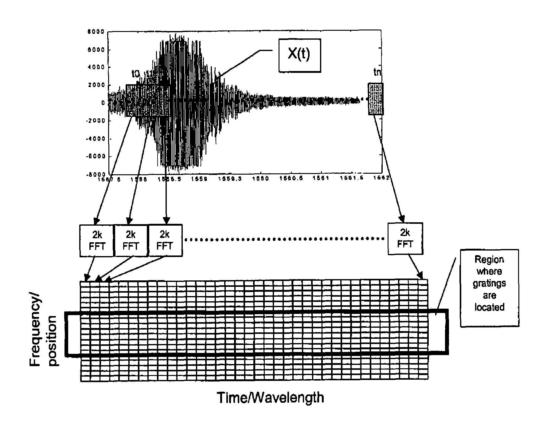
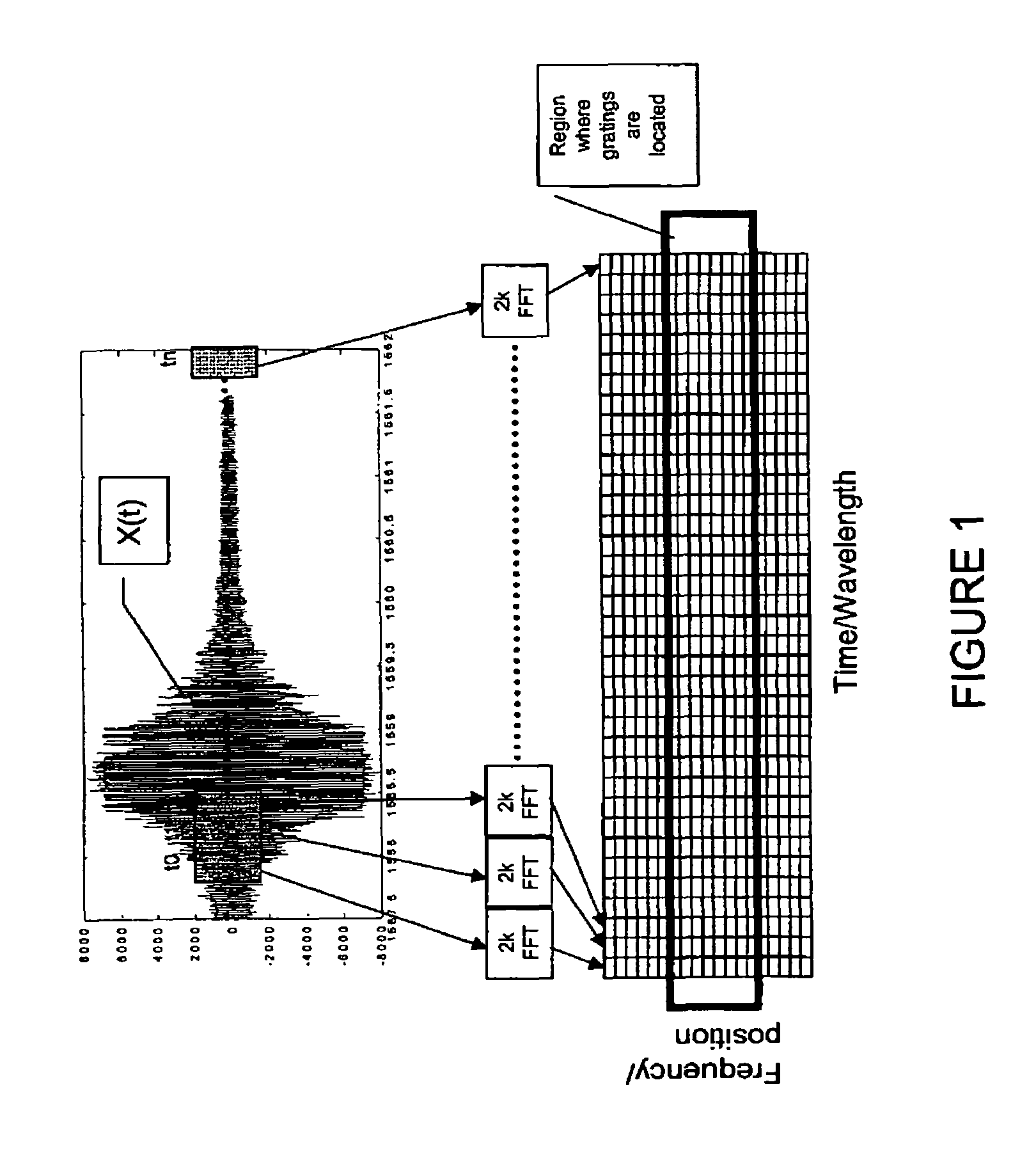
[0017]FBG sensors operate under the principle that a change in strain or temperature alters the sensor grating spacing which shifts the reflected wavelength proportionally. To measure wavelength shifts that result directly from changes in temperature or strain, OFDR FBG sensor systems must include a light source that continuously interrogates the reflection spectrum and a detection module that records the shifts in the peak reflectivity versus wavelength.

[0018]The interrogation refresh rate for OFDR FBG sensor systems depend on the speed of the optical source, the bandwidth of the detectors, the data acquisition rate, and the rate at which the analysis of the wavelength shift can be performed. Due to the latter factor, the rate at which the analysis of the wavelength shift can be performed, current OFDR FBG sensor systems cannot effectively be employed for in situ aerospace systems. This is due to the fact that current OFDR FBG sensor systems have a refresh rate of about 1 scan per ...


PUM

PropertyMeasurementUnit
wavelength Optical Frequency Domain Reflectometryaaaaaaaaaa
time periodaaaaaaaaaa
timeaaaaaaaaaa

Abstract

The invention provides a method of obtaining the FBG data in final form (transforming the raw data into frequency and location data) by taking the raw FBG sensor data and dividing the data into a plurality of segments over time. By transforming the raw data into a plurality of smaller segments, processing time is significantly decreased. Also, by defining the segments over time, only one processing step is required. By employing this method, the refresh rate of FBG sensor systems can be improved from about 1 scan per second to over 20 scans per second.

Description

STATEMENT OF GOVERNMENT INTEREST[0001]The invention described herein may be manufactured and used by or for the Government of the United States of America for governmental purposes without payment of any royalties thereon or therefor.BACKGROUND OF THE INVENTION[0002]1. Field of the Invention[0003]The present invention relates generally to improving sensors, more particularly to improving Fiber Bragg Grating (FBG) sensors and most specifically to improving the interrogation refresh rate of fiber bragg grating sensors.[0004]2. Description of the Related Art[0005]FBG sensors, which are basically gratings along optical fibers that act as mirrors to light sources, provide many attractive characteristics compared to other sensing systems. These include their inherent light weight, small size, and immunity to electromagnetic, radiation, and radio-frequency interference.[0006]These features enable using many sensors on a single optical fiber at either interval or arbitrary spacing. Thus, a ...

Claims


Application Information

Patent Timeline
Patent Type & Authority Patents(United States)
IPC IPC(8): G02B6/00G01L1/24G01D5/353G01N21/25G01J1/04H04B10/2519G01B11/16
CPCG01D5/35316G01L1/246
Inventor PARKER, JR., ALLEN R.
Owner NAT AERONAUTICS & SPACE UNITED STATES OF AMERICA AS REPRESENTED BY THE DIRECTOR OF THE
Why Eureka
Try Eureka