Grounding device for a conductive sheath of a cable and method for installing the grounding device

A technology of grounding device and conductive sheath, which is applied in the direction of cable installation, conductive connection, cable accessories, etc., can solve the problems of increasing transition resistance, etc., and achieve the effect of increasing reliability and firm fixing

Inactive Publication Date: 2018-02-09
TYCO ELECTRONICS RAYCHEM GMBH
View PDF6 Cites 0 Cited by
  • Summary
  • Abstract
  • Description
  • Claims
  • Application Information

AI Technical Summary

Problems solved by technology

[0010] This solution is easier to implement, but has the additional problem of requiring, on the one hand, two separate labor-intensive steps to attach the wire and the copper mesh strap, and, on the other hand, that the transition resistance between the ground wire and the lead sheath is determined by Certain material restrictions to define
In cases where the copper mesh tape is not sufficiently securely laid or the lead sheath is not sufficiently cleaned, this can lead to increased transition resistance
[0011] Furthermore, if these known solutions are used together, the problem is that N(A)KBA and N(A)KLEY cables must be differentiated separately and two different grounding systems must be produced and provided

Method used


Image

  • Grounding device for a conductive sheath of a cable and method for installing the grounding device
  • Grounding device for a conductive sheath of a cable and method for installing the grounding device
  • Grounding device for a conductive sheath of a cable and method for installing the grounding device

Examples


Embodiment Construction

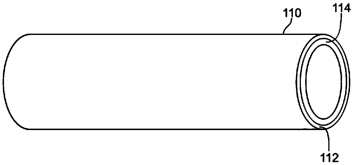
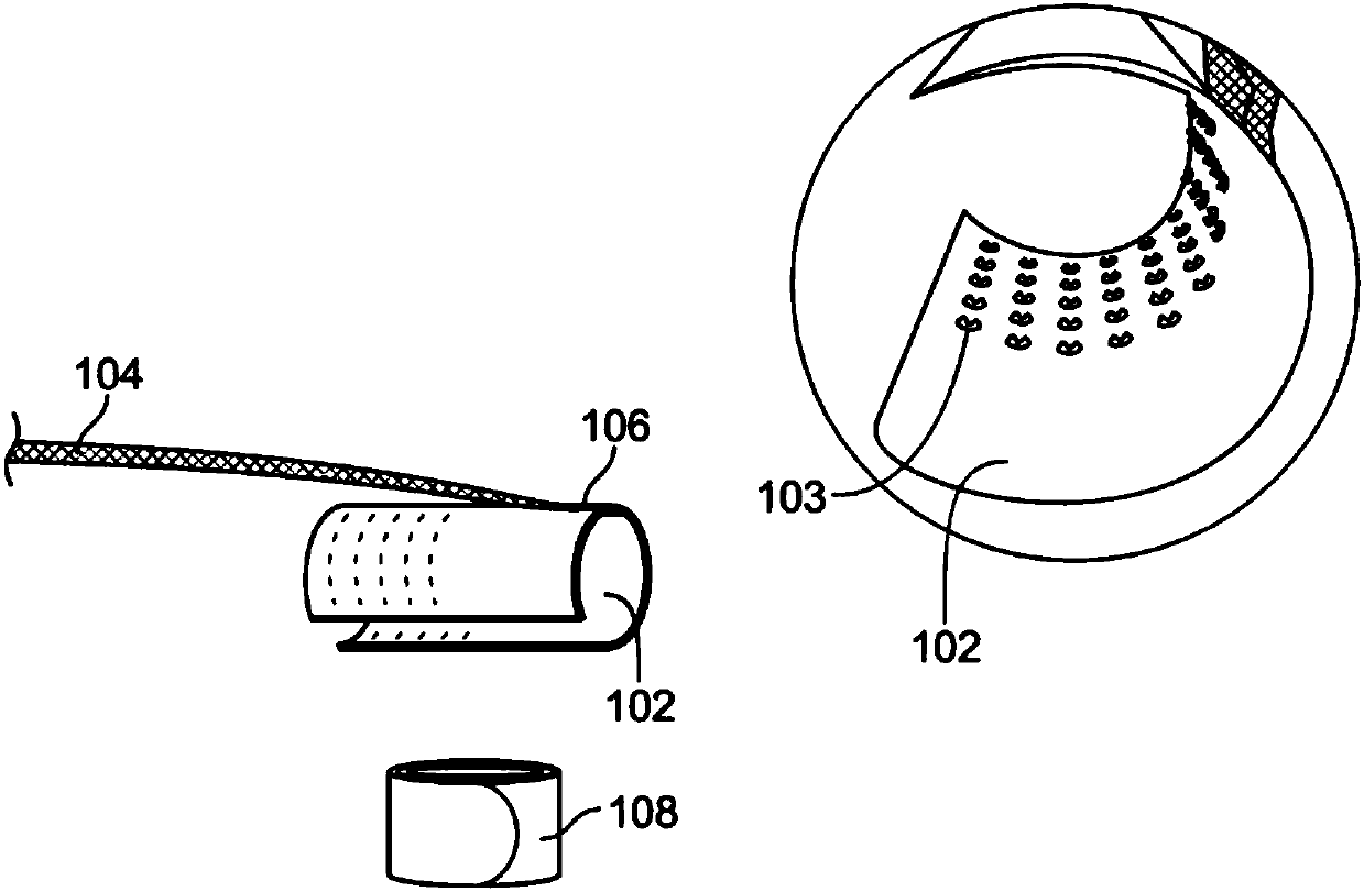
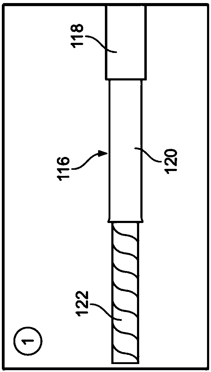
[0036] First, by means of figure 1 The elements required for the grounding device according to the invention are described. Such as figure 1 As shown, the grounding device 100 (the various parts of which are shown here) includes a contact element 102 that is securely connected to a ground wire 104 . This ground line 104 constitutes a connection line connectable at an end region (not shown) to a defined ground point. The contact element 102 has a substantially C-shaped cross-sectional shape such that it can surround the cable perimeter in the installed state (not shown). The ground wire 104 is securely connected to the contact element by a solder connection 106 . To fix the stuck-on contact element 102 to the cable, according to the invention, a coil spring 108 is provided as a retaining element.

[0037] figure 2 show figure 1 Detail view of middle contact element 102. In order to achieve particularly good electrical contacting of the conductive cable sheath, contact p...


PUM


Abstract

The present invention relates to a grounding device for a conductive sheath of an electric cable, in particular for an aluminum or lead sheath, as used in connection with a low voltage cable. This grounding device is particularly useful, for example, when connecting a four-conductor or three-conductor ground cable to a four-conductor composite cable, and especially in the construction of a corresponding transition sleeve for this type of connection. A grounding device (100) for a conductive sheath (120) of a cable (116) has a contact element (102) with a connection wire (104) for connection to a ground point, the contact element (102) being made as In the installed state, it at least partially surrounds the circumference of the cable. Furthermore, a holding element (108, 110) is provided for pressing the contact element (102) onto the conductive cable sheath, which holding element (108, 110) is made such that it surrounds the contact element (102) from the outside in the mounted state , and a defined electrical contact is made between the contact element (102) and the conductive sheath (120).

Description

technical field [0001] The invention relates to a grounding device for a conductive sheath of a cable, in particular for an aluminum or lead sheath, as used in connection with low-voltage and medium-voltage cables, in particular for potential equalization in the case of medium-voltage cables. This grounding device is of importance, for example, when connecting a four-conductor or three-conductor ground cable to a four-conductor composite cable, and in particular in the construction of corresponding transition sleeves for this type of connection. [0002] However, the invention can also be used for the termination of aluminum or lead coated cable ends. Background technique [0003] DE 27 45 832 A1 discloses a connector for connecting a ground conductor to a metal sheath of an electrical conductor, which has a C-shaped sleeve made of a flexible conductive material with a first bent section and a second curved section. The C-shaped sleeve is deformed and bent completely aroun...

Claims


Application Information

Patent Timeline
Patent Type & Authority Patents(China)
IPC IPC(8): H01R4/64H01R4/26H02G15/068
CPCH01R4/646H01R4/26H02G15/068H02G15/188
Inventor D.赫利奇K-P.贝尼基
Owner TYCO ELECTRONICS RAYCHEM GMBH
Why Eureka
Try Eureka