Lateral positioning bending mold

A technology of bending die and side positioning, which is applied in the direction of forming tools, manufacturing tools, metal processing equipment, etc., can solve the problems of increasing production costs and increasing the amount of materials used.

Inactive Publication Date: 2015-07-22
昆山荣科钣金科技有限公司
View PDF6 Cites 2 Cited by
  • Summary
  • Abstract
  • Description
  • Claims
  • Application Information

AI Technical Summary

Problems solved by technology

[0003] The existing bending processing technology corrects the parts with unconventional shapes into parts with conventional shapes by adding micro-connections and other methods. When bending, you can use the backing after bending. Although the existing technology and methods can achieve product bending effect, but virtually increases the amount of material used, while increasing the production cost, after the bending is completed, it is necessary to remove the micro-connection, and at the same time increase the labor, the existing technology has not solved these problems

Method used


Image

  • Lateral positioning bending mold
  • Lateral positioning bending mold

Examples


Embodiment Construction

[0017] The present invention will be specifically introduced below in conjunction with the accompanying drawings and specific embodiments.

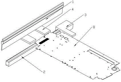
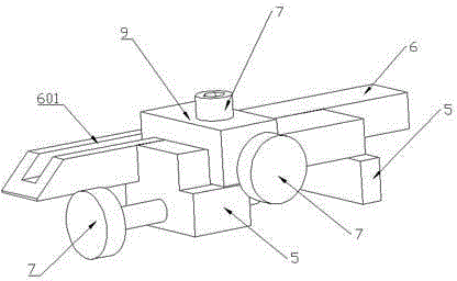
[0018] Side positioning bending mold, including: bending upper die 1, bending lower die 2, side backing 3 fixed on bending lower die 2, rear backing 4 aligned with product 8 bending positioning points; side backing 3 includes : fixed on the lower mold fixing seat 5 of the lower bending die 2, an adjusting piece for adjusting the distance between the side backing 3 and the product 8; The adjustable side block 6 is provided with a chute 601, the position of the adjustable side block 6 is adjusted through the chute 601, and the locking screw 7 is used to fix it to ensure that the product 8 can be completely aligned with the side 3 when bending. Alignment, it needs to be explained that the lower mold fixed block 5 and the adjustable side block 6 are connected through the connecting block 9; the connecting block 9 is clipped in the chute 601 o...


PUM


Abstract

The invention discloses a lateral positioning bending mold. The lateral positioning bending mold comprises an upper bending mold body, a lower bending mold body, lateral abutting parts fixed to the lower bending mold body and back abutting parts aligned with bent positioning points of a product. Each lateral abutting part comprises a lower mold fixing base fixed to the lower bending mold body and an adjustment piece for adjusting the distance between the lateral abutting part and the product. The lateral positioning bending mold is suitable for products in various shapes; accurate positioning is achieved through the lateral abutting parts and the back abutting parts, the bending accuracy is guaranteed, micro-connection does not need to be additionally arranged, cost is saved, and the bending efficiency is improved.

Description

technical field [0001] A die, in particular a side positioning bending die. Background technique [0002] With the continuous acceleration of industrialization and automation, sheet metal parts have been widely used in automobiles, ships, home appliances, kitchen utensils, and aviation equipment. With the gradual rise of domestic machinery manufacturing industry, communication electronics industry, automobile and shipbuilding industries, It also drives the rapid development of the sheet metal processing industry, so the shapes and specifications of sheet metal parts are increasing, and the technical requirements for bending are also getting higher and higher. For parts similar to triangular shapes, the backing cannot be positioned after bending The bending size is already a major difficulty for this type of product. For parts with similar special shapes, how to ensure the bending accuracy has become a difficult problem that must be solved. [0003] The existing bending proc...

Claims


Application Information

Patent Timeline
IPC IPC(8): B21D37/10
CPCB21D37/10
Inventor 王伟明戴秋生杨宏
Owner 昆山荣科钣金科技有限公司
Why Eureka
Try Eureka