Semi-automatic steel bar bending machine

A steel bending and semi-automatic technology, applied in the field of steel bending machines, can solve the problems of inability to control the bending angle of steel bars, narrow application range, etc., and achieve the effects of low noise, reasonable size and position design, and expanded application range.

Inactive Publication Date: 2017-02-22
FUZHOU COLLEGE OF FOREIGN STUDIES & TRADE
View PDF8 Cites 2 Cited by
  • Summary
  • Abstract
  • Description
  • Claims
  • Application Information

AI Technical Summary

Problems solved by technology

However, this steel bar bending machine cannot control the bending angle of the steel bar very well, and in addition, it can only bend the steel bar to a certain fixed value of the bending radius of curvature, so the scope of application is narrow

Method used


Image

  • Semi-automatic steel bar bending machine
  • Semi-automatic steel bar bending machine
  • Semi-automatic steel bar bending machine

Examples


Embodiment 1

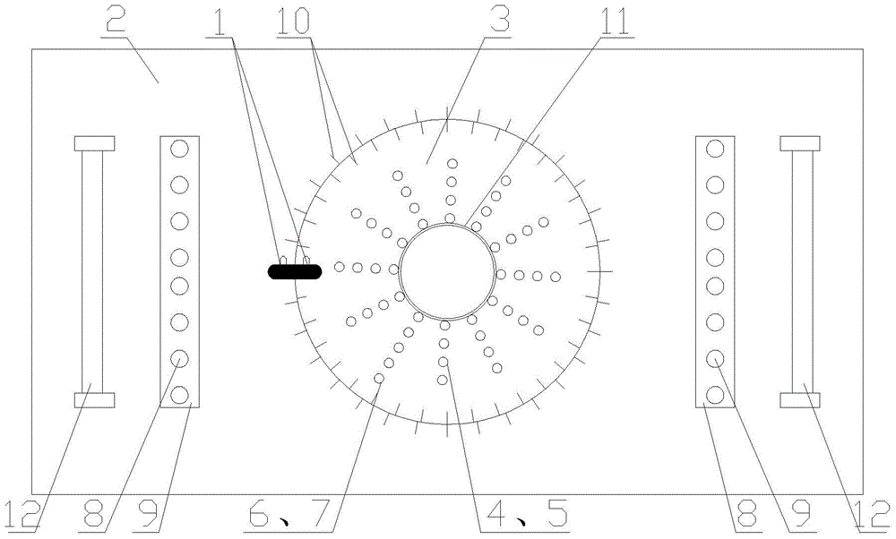
[0023] A semi-automatic steel bar bending machine such as figure 1 As shown, it includes a machine tool, the upper part of the machine tool is provided with a work disk 2, and the work disk 2 is connected with the machine tool. A rotating disk 3 is arranged at the center of the working disk 2, and the rotating disk 3 is connected with a power mechanism inside the machine tool, and the power mechanism can drive the rotating disk 3 to rotate around its own axis. A number of positioning shaft holes 5 and clamping shaft holes 7 are evenly distributed on the rotating disc 3 along the circumferential direction of the rotating disc 3, and the distance between the positioning shaft holes 5 and the clamping shaft holes 7 is adapted to the diameter of the steel bar to be bent , a number of positioning shaft holes 5 are distributed in a circle on the rotating disk 3, and the center of the circularly distributed positioning shaft holes 5 coincides with the center of the rotating disk 3; ...

Embodiment 2

[0026] On the basis of Embodiment 1, scale lines 10 are also provided on the work disk 2 and the rotating disk 3, and the scale line 10 lines on the rotating disk are more than the scale line 10 lines on the work disk 2, and the work disk 2 "0" scale mark 1 is all marked on the rotating disc 3.

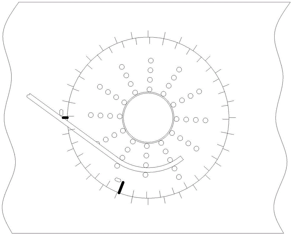
[0027] In this embodiment, the number of scale lines 10 on the working disk 2 is 32, and the angle between two adjacent scale lines 10 on the working disk 2 is 11.25°; the number of lines on the rotating disk 10 is 36, The angle between two adjacent scale marks 10 on the rotating disk is 10°. When the "0" scale line 1 of the working disk 2 and the rotating disk 3 coincide, the angle between the first scale line 10 is 1.25°. like figure 1 As shown, at this time, the "0" scale line 1 of the working disk 2 and the rotating disk 3 coincides, and the steel bar does not bend; but as figure 2 As shown, at this time, the "0" scale line 1 of the working disk 2 and the rotating disk 3 are n...

Embodiment 3

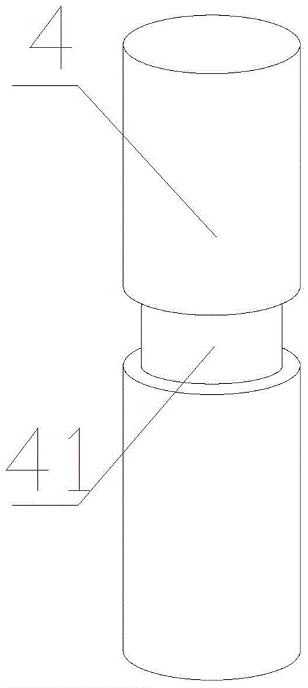
[0029] On the basis of the first or second embodiment, the positioning shaft 4 is provided with a positioning collar 41 ; the clamping shaft 6 is provided with a clamping collar 61 . The positioning collar 41 is set on the positioning shaft 4, which can effectively prevent the steel bar from slipping during the bending process, ensuring the bending accuracy and bending quality of the semi-automatic steel bar bending machine; the clamping collar 61 is provided on the clamping shaft 6, which can Further prevent the steel bar from slipping during bending.


PUM


Abstract

The invention discloses a semiautomatic steel bar bender, which relates to the technical field of steel bar-bending equipment. The invention aims to provide the semiautomatic steel bar bender which can deal with steel bars with different bending radii. The technical scheme of the invention is as follows: the semiautomatic steel bar bender comprises a machine bed, a working plate which is connected with the machine bed is arranged on the top of the machine bed, a rotary disk is arranged at the center of the working plate, the rotary disk is connected with a power mechanism in the machine bed and can rotate around the axis of the rotary disk, a plurality of positioning shaft holes and clamping shaft holes are evenly distributed along the circumferential direction of the rotary disk on the rotary disk, the positioning shaft holes form a plurality of concentric circles on the rotary disk, positioning shafts and clamping shafts are respectively correspondingly placed in the positioning shaft holes and the clamping shaft holes, backing pin blocks and rollers are arranged on both sides of the working plate, and backing pins are arranged on the backing pin blocks. The invention is applicable to steel bar bender.

Description

technical field [0001] The invention relates to the technical field of steel bar bending and forming equipment, in particular to a steel bar bending machine. Background technique [0002] With the gradual development of my country's economic construction, large-scale construction projects are being carried out all over the country to build various residential buildings, office buildings, road works and other projects under construction. A large number of steel bars are bent. For the bending of steel bars, the traditional method is mainly to operate manually, but manual bending of steel bars not only consumes a lot of manpower, but also takes up a lot of construction space. Therefore, in order to solve this problem, there has been a commonly used steel bar processing machine in the prior art—a steel bar bending machine. The steel bar bending machine mainly includes a fuselage and a working disc that is positioned at the top of the fuselage and can rotate around its central ax...

Claims


Application Information

Patent Timeline
Patent Type & Authority Patents(China)
IPC IPC(8): B21F1/00
Inventor 刘若福陈宇鹏陈瑜沈镇乾
Owner FUZHOU COLLEGE OF FOREIGN STUDIES & TRADE
Why Eureka
Try Eureka