
Flanging and bending equipment for metal plate shell of range hood

A machine sheet metal and equipment technology, which is applied in the field of flanging and bending equipment for range hood sheet metal shells, can solve the problems of increased scrap rate, low work efficiency, and high labor intensity, and achieve the effect of precise and fast positioning

Pending Publication Date: 2021-06-29
南京英田激光科技有限公司
View PDF0 Cites 2 Cited by
  • Summary
  • Abstract
  • Description
  • Claims
  • Application Information

AI Technical Summary

Problems solved by technology

Usually, the operator uses the ordinary bending machine to perform the flanging and bending operation from the stamping to the semi-finished product. This operation method is very inefficient and labor-intensive. It leads to the deviation of the formed product, which leads to an increase in the scrap rate of the subsequent laser automatic welding process.
At the same time, the surface of some range hood sheet metal is not regular. The edge to be bent is not a flat plate with an inner hook on it. The flanging causes interference, so a flanging and bending equipment for the range hood sheet metal shell that can be positioned accurately and avoid irregular misalignment is needed

Method used


Image

  • Flanging and bending equipment for metal plate shell of range hood
  • Flanging and bending equipment for metal plate shell of range hood
  • Flanging and bending equipment for metal plate shell of range hood

Examples


specific Embodiment

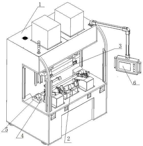
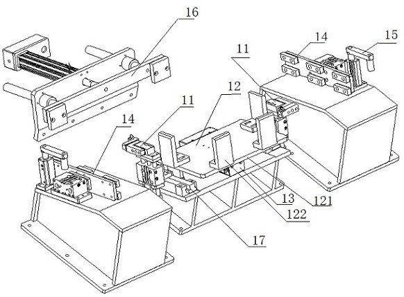
[0044] When feeding, put the edge of the sheet metal to be bent into the surface of the inner lower turning die assembly, and the cavity of the sheet metal is inserted into the multiple pins of the auxiliary feeding assembly, and manually adjust the position of the sheet metal until the sheet metal The through hole on the surface coincides with the pin hole on the surface of the main and auxiliary positioning pin assembly, and inserts the pin column into the through hole of the sheet metal and the main and auxiliary positioning pin hole. The clamping cylinder presses the sheet from above, and the cylinders on the left and right mounting brackets press the sheet from both sides. At this time, after the sheet is fixed, the upper pressing die assembly falls, driving the upper bending die to press the sheet and fold it. Bending position, then rotate left and right to compress the cylinder, and the cylinder on the left and right mounting brackets releases the sheet metal at the same...


PUM


Abstract

The invention discloses flanging and bending equipment for a metal plate shell of a range hood. The flanging and bending equipment comprises an equipment body, a product positioning tool, an upper pressing cutting die assembly, a lower pressing cutting die and a lower overturning cutting die assembly, wherein the product positioning tool, the upper pressing cutting die assembly, the lower pressing cutting die and the lower overturning cutting die assembly are mounted on the surface of the body. An auxiliary feeding assembly and a rear auxiliary feeding assembly of the product positioning tool are used for feeding and fixing. Left and right mounting supports are located on the left side and the right side of a to-be-machined metal plate and used for clamping the metal plate. A bending upper cutting die of the upper pressing cutting die assembly is located at the upper end of the bent edge of the fed to-be-machined metal plate and used for pressing the upper portion of a to-be-bent line. The lower overturning cutting die assembly rotates the to-be-bent edge upwards. According to the flanging and bending equipment for the metal plate shell of the range hood, the bending line position of the metal plate can be accurately adjusted, and the bending precision of metal plates made of different materials is guaranteed.

Description

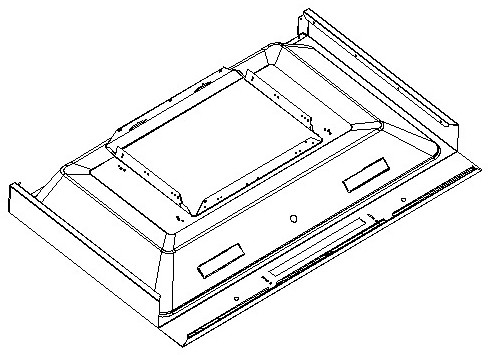
technical field [0001] The invention relates to the field of metal machining, in particular to a flanging and bending device for a sheet metal shell of a range hood. Background technique [0002] The semi-finished product after stamping of the range hood sheet metal casing needs to be bent. The finished product of the range hood sheet metal casing usually has a four-sided flanging structure and a through-through structure in the middle, such as figure 1 . In the actual production and processing process, the sheet metal casing of the range hood can only be flanged on three sides after the stamping process. At this time, it is necessary to add a bending process after the stamping process to complete the flanging of the fourth side. Usually, the operator uses the ordinary bending machine to perform the flanging and bending operation from the stamping to the semi-finished product. This operation method is very inefficient and labor-intensive, and it will be caused by personnel ...

Claims


Application Information

Patent Timeline
Patent Type & Authority Applications(China)
IPC IPC(8): B21D37/10B21D37/04B21D43/00
CPCB21D37/10B21D37/04B21D43/003
Inventor 赵俊飞周子元
Owner 南京英田激光科技有限公司
Learn More