an integrated sensor

An integrated sensor and sensing technology, applied in the field of integrated sensors, can solve problems such as poor contact of each node, achieve the effect of reducing off-line problems, reasonable structure, and improving service life

Active Publication Date: 2016-06-22
三桥惠(佛山)新材料有限公司
View PDF6 Cites 0 Cited by
  • Summary
  • Abstract
  • Description
  • Claims
  • Application Information

AI Technical Summary

Problems solved by technology

[0003] This structural setting leads to the fixed connection of each working part with the mounting plate, and the pressure of the inner pot drives the selection, and then produces up and down movements to realize no pot and detection. The continuous bending and extension of the lead wires of the working parts will easily cause the problem of poor contact at each node.

Method used


Image

  • an integrated sensor
  • an integrated sensor
  • an integrated sensor

Examples


Embodiment Construction

[0054] The present invention will be further described below in conjunction with the accompanying drawings.

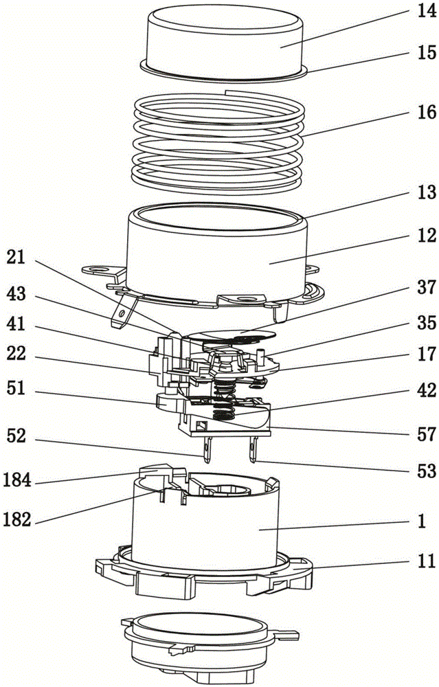
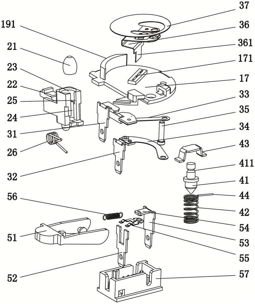
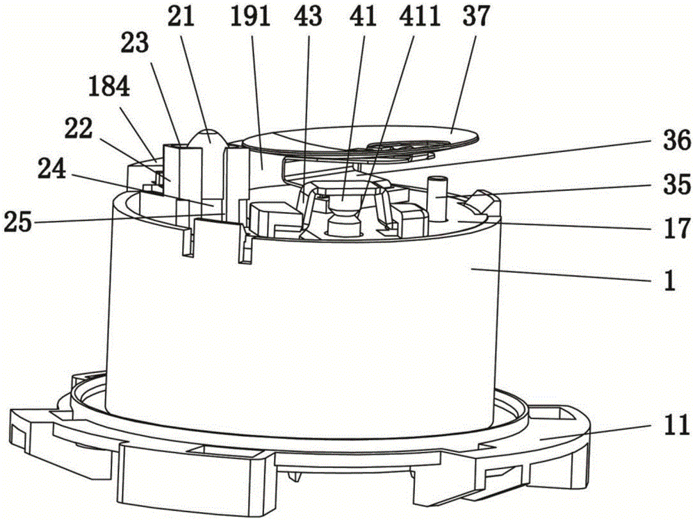
[0055] Such as Figure 1-6As shown, an integrated sensor according to the present invention includes a base 1, the base 1 is provided with sensing components, the upper end of the base 1 is provided with an upper cover 14 that moves independently relative to it, and the base 1 and the upper cover 14 A compression spring 16 is provided between them; the upper cover 14 interferes with the sensing components in the base 1 during the downward stroke; as Figure 5 As shown, the base 1 is fixedly installed in the electric heating vessel 61 and the sensing part is electrically connected to the main control board of the electric heating vessel 61. The upper cover 14 can be moved up and down on the heating tray 63, and the upper cover 14 is connected to the base in the initial state. The sensing parts in 1 are relatively non-contact. The inner pot 62 is put into the electric h...


PUM


Abstract

The invention relates to the technical field of temperature control sensors, in particular to an integrated sensor. Including the base, the base is provided with sensing components, the upper end of the base is covered with a cover that moves independently of it, and a compression spring is provided between the base and the cover; Sensing components conflict with linkage. The invention has a reasonable structure. When the temperature of the inner pot rises to the set value of anti-dry heating, the thermistor cuts off the circuit of the main control board to realize power-off protection, and the circuit can be connected again after the contact piece cools down; Limit, the temperature-sensing plate activates the thermal fusing function, directly melts the fuse core through high temperature, and forcibly cuts off the heating circuit to achieve the final protection; the temperature-sensing sheet and insulating bracket are used as stress response components to reduce the off-line problem of lead solder joints and improve the overall service life .

Description

technical field [0001] The invention relates to the technical field of temperature control sensors, in particular to an integrated sensor. Background technique [0002] Chinese patent CN201422761Y discloses a micro switch type anti-dry device, including a mounting cup, a micro switch and a switch support plate, the micro switch is set in the mounting cup, the mounting cup is installed on the switch support plate, and installed There is a return spring between the cup and the switch support plate, and the switch support plate is fixed on the installation base. When the cup is released, the heating circuit is disconnected. [0003] This structural setting leads to the fixed connection of each working part with the mounting plate, and the pressure of the inner pot drives the selection, and then produces up and down movements to realize no pot and detection. The continuous bending and extension of the lead wires of the working parts will easily cause the problem of poor contact...

Claims


Application Information

Patent Timeline
Patent Type & Authority Patents(China)
IPC IPC(8): H05B1/02
CPCH05B1/02H05B1/0205H05B1/0222H05B1/0261
Inventor 刘利龙克文
Owner 三桥惠(佛山)新材料有限公司
Why Eureka
Try Eureka