A sensor trigger structure

A sensor and temperature sensor technology, applied in the field of sensor trigger structure, can solve the problems of lead wire and solder joint bending and fracture, desoldering, high defective rate of sensor, etc., to reduce off-line problems, improve service life, trigger action Accurate and stable effect

Inactive Publication Date: 2017-03-15
FOSHAN CHUANDONG MAGNETOELECTRICITY +1
View PDF1 Cites 0 Cited by
  • Summary
  • Abstract
  • Description
  • Claims
  • Application Information

AI Technical Summary

Problems solved by technology

[0003] There are many defects in this structure setting. In practical application, each working part in the sensor is fixedly connected with the installation cup. Driven by the pressure of the inner pot, it generates up and down movements to realize potless detection. The position changes continuously, and the lead wires between the working parts and the circuit are continuously bent and extended, and the lead wires and solder joints are prone to bending, fracture and desoldering, resulting in a high rate of defective products in the sensor.

Method used


Image

  • A sensor trigger structure
  • A sensor trigger structure

Examples


Embodiment Construction

[0021] The present invention will be further described below in conjunction with the accompanying drawings.

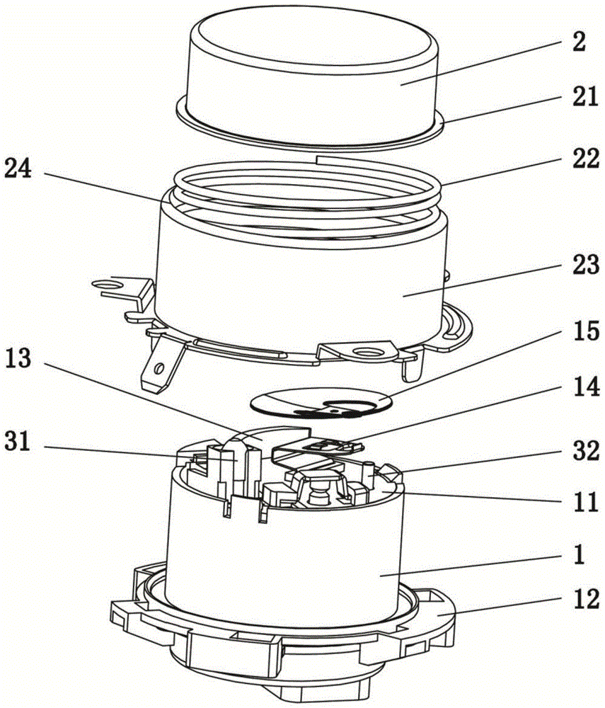
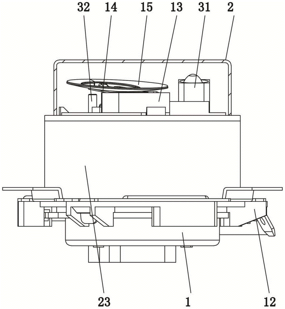
[0022] A sensor triggering structure, comprising a base 1, the base 1 is provided with a heat-sensitive component 31 and an anti-dry device, the upper end of the base 1 is provided with an upper cover 2 that acts independently of it, and an upper cover 2 and the base 1 are provided There is a compression spring 22; the upper port of the base 1 is provided with a fixed plate 11 corresponding to the upper cover 2, and a temperature-sensitive sheet 15 that can move up and down is provided between the fixed plate 11 and the upper cover 2, and the temperature-sensitive sheet 15 is connected to the fixed Elastic reeds 14 are connected between the plates 11 , and the heat-sensitive component 31 is arranged on the fixed plate 11 on one side of the temperature-sensing plate 15 , and the heat-sensitive component 31 is arranged in cooperation with the upper cover 2 . The above co...


PUM


Abstract

The invention relates to the technical field of temperature control sensors, in particular to a sensor triggering structure. The sensor triggering structure comprises a base. A thermo-sensitive assembly and an anti-dry burning device are arranged inside the base. The upper end of the base is provided with an upper cover which independently acts relative to the base. A compression spring is arranged between the upper cover and the base. The upper end opening of the base is provided with a fixed plate corresponding to the upper cover. An elastic reed is arranged between a temperature sensing sheet and the fixed plate. A triggering component of the anti-dry burning component is arranged on the fixed plate arranged under the temperature sensing sheet. The thermo-sensitive assembly is arranged on one side, provided with the temperature sensing plate, of the fixed plate. According to the sensor triggering structure, the structure is reasonable, the upper cover is displaced up and down along a guiding shell relative to the base, and the upper cover is prevented from horizontally shifting in the triggering process so that the sensitivity of a sensor cannot be influenced. In the downward pressing process of the upper cover, the upper cover is in sequential contact with the thermo-sensitive assembly and the temperature sensing piece, and the triggering action is accurate and stable. Due to the fact that a sensing component inside the base is fixedly arranged, the problem of thread loosing of lead welding spots can be effectively lowered, and the service life and the yield are improved.

Description

technical field [0001] The invention relates to the technical field of temperature control sensors, in particular to a sensor trigger structure. Background technique [0002] Chinese patent CN201422761Y discloses a micro switch type anti-dry device, including a mounting cup, a micro switch and a switch support plate, the micro switch is set in the mounting cup, the mounting cup is installed on the switch support plate, and installed There is a return spring between the cup and the switch support plate, and the switch support plate is fixed on the installation base plate. When in use, the micro switch is operated under the installation cup to connect the heating circuit on the installation base plate. There are thermal components connected in series on the heating circuit, and the installation cup When released, the heating circuit is disconnected. [0003] There are many defects in this structural arrangement. In practical applications, the working parts in the sensor are f...

Claims


Application Information

Patent Timeline
Patent Type & Authority Patents(China)
IPC IPC(8): H01H37/46
CPCH01H37/46
Inventor 刘利龙克文
Owner FOSHAN CHUANDONG MAGNETOELECTRICITY
Why Eureka
Try Eureka