
Thermal flow rate measurement device

A technology of thermal flow, measuring equipment, applied in the direction of measuring fluid velocity using thermal variables, measuring flow/mass flow, liquid/fluid solid measurement, etc.

Active Publication Date: 2015-07-22
ENDRESS HAUSER FLOWTEC AG
View PDF5 Cites 4 Cited by
  • Summary
  • Abstract
  • Description
  • Claims
  • Application Information

AI Technical Summary

Problems solved by technology

However, these sensors exhibit worse characteristics in water than the earlier mentioned sensors

Method used


Image

  • Thermal flow rate measurement device
  • Thermal flow rate measurement device
  • Thermal flow rate measurement device

Examples


Embodiment Construction

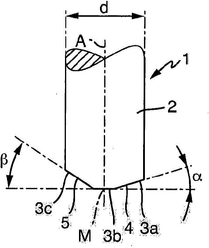
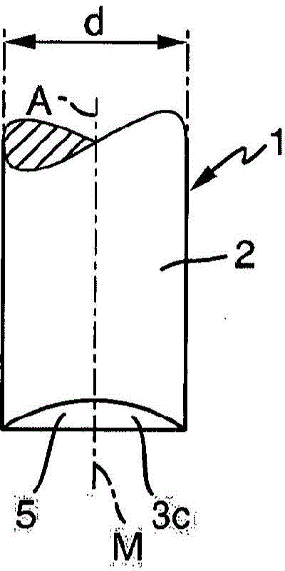
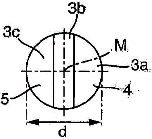
[0045] figure 1 A sensor of a thermal flow measuring device is shown, wherein the sensor is embodied as a thermal mass flow sensor 1 .

[0046] Conventional thermal flow measuring devices usually use two heatable resistance thermometers, which are implemented as identical as possible and are usually arranged on pin-shaped metal sleeves (so-called stingers) In or arranged in a cylindrical metal sleeve, in thermal contact with the medium flowing through the measuring tube or through the pipeline. For industrial applications, two resistance thermometers are usually installed in the measuring tube; however, resistance thermometers can also be installed directly in the pipeline. One of the two resistance thermometers is a so-called active sensor element, which is heated by means of a heating unit. Provided as heating unit are any additional resistance heaters or, in the case of resistance thermometers which are resistance elements, e.g. The change is heated. The second resista...


PUM


Abstract

The invention relates to a thermal flow rate measurement device for determining and / or monitoring a thermal mass flow of a measurement medium through a measurement tube, comprising a sensor having a first heatable resistance thermometer and at least one second heatable resistance thermometer, wherein the sensor has a longitudinal axis (A) and an end face (3), which is divided into at least two segments (3a-3c) arranged next to each other, wherein a surface normal vector of at least one first segment encloses an angle (a) of at least 5° with the longitudinal axis (A) of the sensor. The invention further relates to the use of a thermal flow rate measurement device.

Description

technical field [0001] The invention relates to a thermal flow measuring device as defined in the preamble of claim 1 and to the use of such a thermal flow measuring device. Background technique [0002] Sensors for flow measuring devices which operate according to the thermal measurement principle are known. This measuring principle is based on cooling a heated resistance thermometer (hereinafter also referred to as heating or active sensor element) from which the flowing measured medium draws heat away. The energy drawn away is resupplied by increasing the electric heating current. In this way, a constant temperature difference is maintained between the heating and measuring sensor element, thus between the active sensor element and the reference temperature sensor element (hereinafter also referred to herein as measuring or passive sensor element). To maintain this difference, the greater the mass flow, the more energy is required. Therefore, the measured heating curre...

Claims


Application Information

Patent Timeline
Patent Type & Authority Applications(China)
IPC IPC(8): G01P5/12G01F1/684G01F1/692
CPCG01F1/684G01P5/12G01F1/692G01F1/6842G01F1/69
Inventor 托比亚斯·波尔斯特凡·盖伯蒂埃尔帕纳约蒂斯·帕帕萨纳修阿克塞尔·普福汉诺·舒尔特海斯
Owner ENDRESS HAUSER FLOWTEC AG
Learn More