

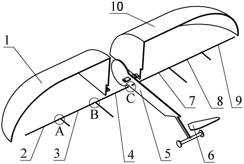
Design of a Foldable Flapping Wing and Fixed Wing Coupling Aircraft
A fixed-wing and aircraft technology, applied in the design method and manufacturing field of micro-miniature aircraft, can solve problems such as low aerodynamic efficiency, and achieve the effects of increasing effective load, facilitating transportation and storage, and maintaining good maintainability
- Summary
- Abstract
- Description
- Claims
- Application Information
AI Technical Summary
Problems solved by technology
Method used
Image

Examples
Embodiment
[0052] Provide the design dimensions of each parameter of a group of micro-aircraft of the present invention in this example, in conjunction with the above manufacturing steps about the micro-aircraft of the present invention:
[0053] In the first step, the fuselage, rods and fixed wings are all made of carbon fiber plates or rods, and the membranes of the flapping wings and empennage are made of polyvinyl chloride film;
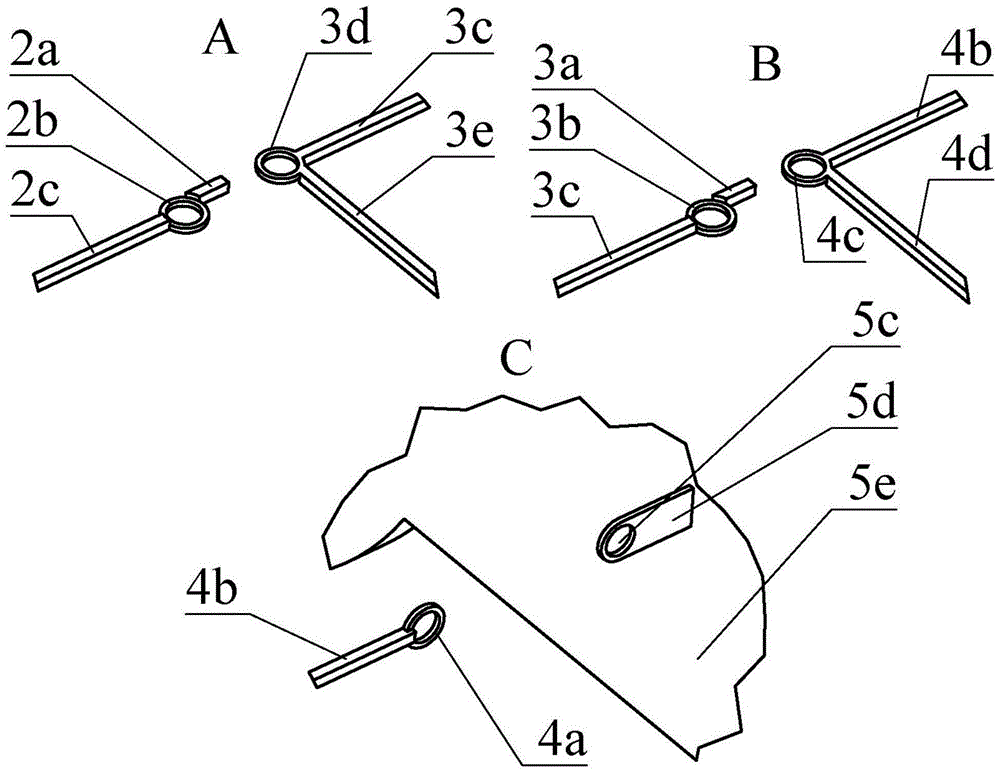
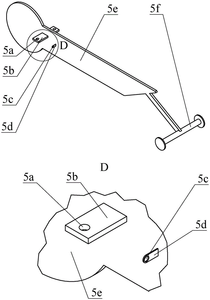
[0054]In the second step, the cross-section of the front edge 4b of the left inner rod is a square with a side length of 2mm and a length of 150mm, the length of the left inner rod limit rod 4d is 120mm, and the inner and outer diameters of the left inner rod outer ring 4c are 2mm and 4mm respectively; The length of the left mid-rod limit block 3a is 10mm, and the length of the left mid-rod limit rod 3e is 60mm; the axis of the left horizontal ear hole 5a and the left longitudinal ear hole 5c of the fuselage is 10mm away from the center plane of the fusela...
PUM
 Abstract
Description
Claims
Application Information