Forward tilted turbine nozzle

a turbine nozzle and forward tilt technology, applied in the direction of liquid fuel engines, efficient propulsion technologies, machines/engines, etc., can solve the problems of increasing fuel consumption and constant increase in jet fuel costs, and achieve the effect of improving efficiency

Active Publication Date: 2006-12-07
GENERAL ELECTRIC CO
View PDF29 Cites 33 Cited by
  • Summary
  • Abstract
  • Description
  • Claims
  • Application Information

AI Technical Summary

Benefits of technology

[0016] A turbine nozzle includes a row of vanes joined to radially outwardly inclined outer and inner bands. Each vane has camber and an acute twist angle for importing swirl in combustion gases discharged at trailing edges thereof. The trailing edges are tilted forwardly from the inner band to the outer band for increasing aerodynamic efficiency.

Problems solved by technology

The cost of jet fuel continually increases, and the need to further maximize efficiency of turbofan engines and reduce fuel consumption becomes ever more challenging in modern aircraft engine design.

Method used


Image

  • Forward tilted turbine nozzle
  • Forward tilted turbine nozzle
  • Forward tilted turbine nozzle

Examples


Embodiment Construction

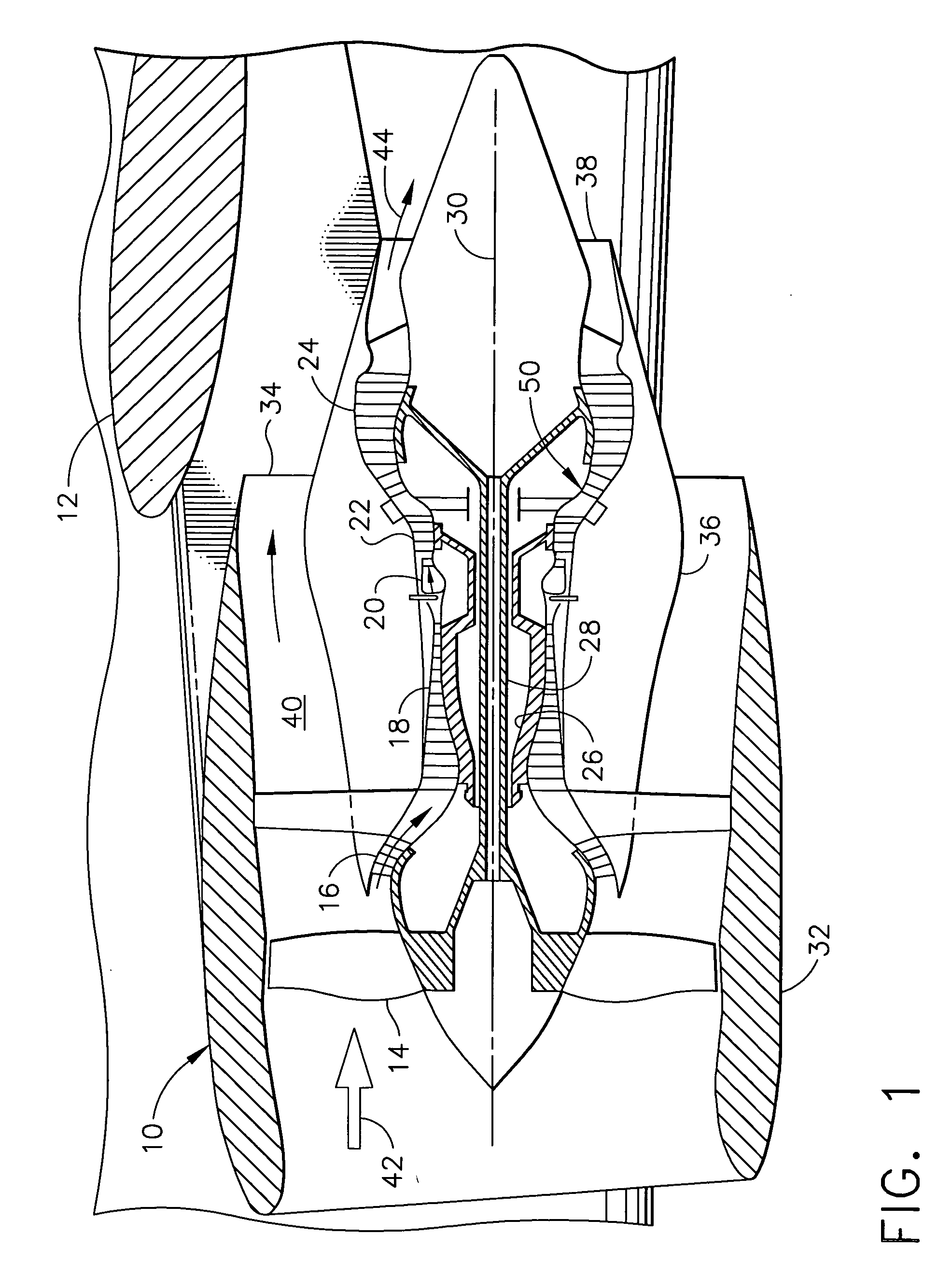
[0023] Illustrated schematically in FIG. 1 is a turbofan engine 10 mounted to the wing 12 of aircraft for providing propulsion thrust therefor. The engine includes in serial flow communication a fan 14, low pressure or booster compressor 16, multistage high pressure axial compressor 18, annular combustor 20, high pressure turbine (HPT) 22, and multistage low pressure turbine (LPT) 24.

[0024] The high pressure compressor 18 is joined to the HPT 22 by a first shaft or rotor 26, and the fan 14 and booster compressor 16 are joined to the LPT 24 by a second shaft or rotor 28 which are concentric with each other, and coaxial about a longitudinal or axial centerline axis 30 of the engine.

[0025] A fan nacelle 32 surrounds the fan 14 and extends aft therefrom to terminate at a distal end in a substantially annular fan outlet or nozzle 34. A core cowl 36 surrounds the compressors 16,18, combustor 20, HPT 22, and LPT 24, and has an annular core outlet or nozzle 38 which is spaced downstream o...


PUM


Abstract

A turbine nozzle includes a row of vanes joined to radially outwardly inclined outer and inner bands. Each vane has camber and an acute twist angle for importing swirl in combustion gases discharged at trailing edges thereof. The trailing edges are tilted forwardly from the inner band to the outer band for increasing aerodynamic efficiency.

Description

BACKGROUND OF THE INVENTION [0001] The present invention relates generally to gas turbine engines, and, more specifically, to aircraft turbofan engines. [0002] Gas turbine engines have evolved into many configurations for powering various forms of commercial and military aircraft. The typical turbofan engine includes in serial flow communication a fan, compressor, combustor, high pressure turbine (HPF), and low pressure turbine (LPT). [0003] Air enters the engine and is pressurized by the fan and compressor and mixed with fuel in the combustor for generating hot combustion gases. Energy is extracted from the combustion gases in the HPT which powers the compressor through an interconnecting shaft. Additional energy is extracted from the combustion gases in the LPT which powers the fan through a second shaft. [0004] The fan is typically disposed inside a fan nacelle that defines a substantially annular bypass duct around the cowl which surrounds the core engine. Air pressurized by the...

Claims


Application Information

Patent Timeline
Patent Type & Authority Applications(United States)
IPC IPC(8): F01D9/00
CPCF01D5/141F01D5/142F01D9/041F02C3/067F05D2250/314Y02T50/671Y02T50/673F05D2220/323F02K3/072Y02T50/60
Inventor ORLANDO, ROBERT JOSEPHMONIZ, THOMAS ORYLEE, CHING-PANGCHERRY, DAVID GLENNBEACOCK, ROBERT JOHNCLIFFORD, WILLIAM LARSONCARSON, SCOTT MICHAEL
Owner GENERAL ELECTRIC CO
Why Eureka
Try Eureka